Loading...
Searching...
No Matches
GenICam™ and advanced features
Introduction
For new applications or to set the device via ImpactControlCenter we recommend to use the GenICam interface layout as it allows the most flexible access to the device features.
After you've set the interface layout to GenICam (either programmed or using ImpactControlCenter), all GenICam controls of the device are available.
- Note
- It depends on the device, which controls are supported. To clarify if your device supports a specific control or property, you can use the interactive "Product Comparison" chapter. Just select the wanted property and click on the button "Rebuild Comparison Table".
In ImpactControlCenter, you can see them in "Setting → Base → Camera → GenICam":
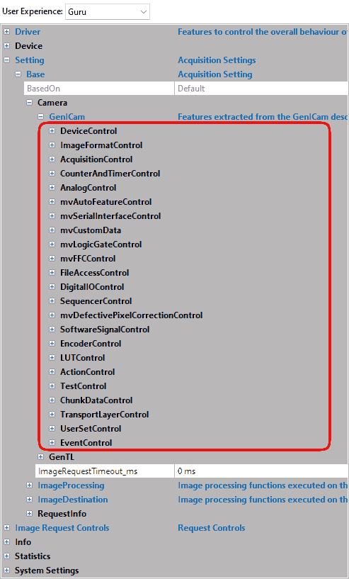
As you can see, there are some controls with and without the prefix "mv".
- "mv" prefix features are unique non-standard features developed by Balluff/MATRIX VISION.
Without "mv" are standard features as known from the Standard Features Naming Convention of GenICam™ properties (SFNC).
All those features are "camera based / device based" features which can also be accessed using the camera with other GenICam / GigE Vision compliant third-party software.
- Note
- In GigE Vision™ timestamps are denoted in "device ticks" but for Balluff/MATRIX VISION devices this equals microseconds.
- Do not mix up the camera based / device based features with the features available in "Setting → Base → Image Processing". Theses features control the Impact Acquire software stack and therefore will introduce additional CPU load.
Device Control
The "Device Control" contains the features like
| Feature name (acc. to SFNC) | Property name (acc. to Impact Acquire) | Description |
| DeviceType | deviceType | Returns the device type. |
| DeviceScanType | deviceScanType | Scan type of the sensor of the device. |
| DeviceVendorName | deviceVendorName | Name of the manufacturer of the device. |
| DeviceModelName | deviceModelName | Name of the device model. |
| DeviceManufacturerInfo | deviceManufacturerInfo | Manufacturer information about the device. |
| DeviceVersion | deviceVersion | Version of the device. |
| DeviceFirmwareVersion | deviceFirmwareVersion | Firmware version of the device. |
| DeviceSerialNumber | deviceSerialNumber | Serial number of the device. |
| DeviceUserID | deviceUserID | User-programmable device identifier. |
| DeviceTLVersionMajor | deviceTLVersionMajor | Major version of the transport layer of the device. |
| DeviceTLVersionMinor | deviceTLVersionMinor | Minor version of the transport layer of the device. |
| DeviceLinkSpeed | deviceLinkSpeed | Indicates the speed of transmission negotiated on the specified Link. |
| DeviceTemperature | deviceTemperature | Device temperature. |
| etc. |
related to the device and its sensor.
This control provides a bandwidth control feature . You have to select DeviceLinkThroughputLimit. Here you can set the maximum bandwidth in KBps.
Balluff offers also some information properties about the
- FPGA
- mvDeviceFPGAVersion
- and the image sensor
- mvDeviceSensorColorMode
A further use case related to the "Device Control" is:
Image Format Control
The "Image Format Control" contains features like
| Feature name (acc. to SFNC) | Property name (acc. to Impact Acquire) | Description |
| SensorWidth | sensorWidth | Effective width of the sensor in pixels. |
| SensorHeight | sensorHeight | Effective height of the sensor in pixels. |
| SensorName | sensorName | Name of the sensor. |
| Width | width | Width of the image provided by the device (in pixels). |
| Height | height | Height of the image provided by the device (in pixels). |
| BinningHorizontal, BinningVertical | binningHorizontal, binningVertical | Number of horizontal/vertical photo-sensitive cells to combine together. |
| DecimationHorizontal, DecimationVertical | decimationHorizontal, decimationVertical | Sub-sampling of the image. This reduces the resolution (width) of the image by the specified decimation factor. |
| TestPattern | testPattern | Selects the type of test image that is sent by the device. |
| etc. |
related to the format of the transmitted image.
With TestPattern, for example, you can select the type of test image that is sent by the device. Here two special types are available:
- mvBayerRaw (the Bayer mosaic raw image)
- mvFFCImage (the flat-field correction image)
Additionally, Balluff offers numerous additional features like:
- mvMultiAreaMode
which can be used to define multiple AOIs (Areas of Interests) in one image.- See also
- The use case Working with multiple AOIs (mv Multi Area Mode) shows how this feature works.
Acquisition Control
The "Acquisition Control" contains features like
| Feature name (acc. to SFNC) | Property name (acc. to Impact Acquire) | Description |
| AcquisitionMode | acquisitionMode | Sets the acquisition mode of the device. The different modes configures a device to send
and can be used for asynchronously grabbing and sending image(s). It works with internal and external hardware trigger where the edge is selectable. The external trigger uses ImageRequestTimeout (ms) to time out.
|
| AcquisitionStart | acquisitionStart | Starts the acquisition of the device. |
| AcquisitionStop | acquisitionStop | Stops the acquisition of the device at the end of the current Frame. |
| AcquisitionAbort | acquisitionAbort | Aborts the acquisition immediately. |
| AcquisitionFrameRate | acquisitionFrameRate | Controls the acquisition rate (in Hertz) at which the frames are captured. Some cameras support a special internal trigger mode that allows more exact frame rates. This feature keeps the frame rate constant to an accuracy of +/-0.005 fps at 200 fps. This is achieved using frames with a length difference of up to 1 us. Please check in the sensor summary if this feature exists for the requested sensor. |
| TriggerSelector | triggerSelector | Selects the type of trigger to configure. A possible option is mvTimestampReset. The use case about mvTimestampReset is available. |
| TriggerOverlap[TriggerSelector] | triggerOverlap | Specifies the type trigger overlap permitted with the previous frame. TriggerOverlap is only intended for external trigger (which is usually non-overlapped: i.e. exposure and readout are sequentially). This leads to minimal latency / jitter between trigger and exposure. Maximum frame rate in triggered mode = frame rate of continuous mode This however leads to higher latency / jitter between trigger and exposure. A trigger will be not latched if it occurs before this moment (trigger is accurate in time). |
| ExposureMode | exposureMode | Sets the operation mode of the exposure (or shutter). |
| ExposureTime | exposureTime | Sets the exposure time (in microseconds) when ExposureMode is Timed and ExposureAuto is Off. |
| ExposureAuto | exposureAuto | Sets the automatic exposure mode when ExposureMode is Timed. |
| etc. |
related to the image acquisition, including the triggering mode.
Additionally, Balluff offers numerous additional features like:
- mvShutterMode
which selects the shutter mode of the CMOS sensors like rolling shutter or global shutter. - mvDefectivePixelEnable
which activates the sensor's defective pixel correction. - mvExposureAutoSpeed
which determines the increment or decrement size of exposure value from frame to frame. - mvExposureAutoDelayImages
the number of frames that the AEC must skip before updating the exposure register. - mvExposureAutoAverageGrey
common desired average grey value (in percent) used for Auto Gain Control (AGC) and Auto Exposure Control (AEC). - mvExposureAutoAOIMode
common AutoControl AOI used for Auto Gain Control (AGC), Auto Exposure Control (AEC) and Auto White Balance (AWB). - mvAcquisitionMemoryMode
Balluff offers three additional acquisition modes which use the internal memory of the camera:- mvPretrigger
which stores frames in memory to be transferred after trigger.
To define the number of frames to acquire before the occurrence of an AcquisitionStart or AcquisitionActive trigger, you can use mvPretriggerFrameCount.- See also
- The use case Recording sequences with pre-trigger shows how this feature works.
- mvPretrigger
- mvAcquisitionMemoryMaxFrameCount
which shows the maximum of frames the internal memory can save.- See also
- The use case Working with burst mode buffer lists some maximum frame counts of some camera models.
- mvSmearReduction
smear reduction in triggered and non-overlapped mode.
- Since
- FW Revision 2.40.2546.0
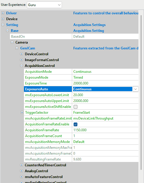
Common properties for AutoExposureControl, AutoGainControl , and AutoWhiteBalance are available via mv Auto Feature Control.
For "Exposure Auto Mode", in ImpactControlCenter just select in "Exposure Auto" "Continuous". Afterwards, you have the possibility to set lower and upper limit, average gray combined with AOI setting:
- mvSmartFrameRecallFrameSkipRatio
When set to a value != 0, the smaller frames get thinned out. AOI requests can still be done for all frames. mvSmartFrameRecallTimestampLookupAccuracy
is needed for the SkipRatio feature since you don't know the timestamps of the internal frames. This value defines the strictness of the timestamp-check for the recalled image (given in us).
Counter And Timer Control
The "Counter And Timer Control" is a powerful feature which Balluff/MATRIX VISION customers already know under the name Hardware Real-Time Controller (HRTC). Balluff/MATRIX VISION cameras provide:
- 4 counters for counting events or external signals (compare number of triggers vs. number of frames; overtrigger) and
- 2 timers.
Counter and Timers can be used, for example,
- for pulse width modulation (PWM) and
- to generate output signals of variable length, depending on conditions in camera.
This achieves complete HRTC functionality which supports following applications:
- frame rate by timer
- exposure time by timer
- pulse width at input
The "Counter And Timer Control" contains features like
| Feature name (acc. to SFNC) | Property name (acc. to Impact Acquire) | Description |
| CounterSelector | counterSelector | Selects which counter to configure. |
| CounterEventSource[CounterSelector] | counterEventSource | Selects the events that will be the source to increment the counter. |
| CounterEventActivation[CounterSelector] | counterEventActivation | Selects the activation mode event source signal. |
| etc. | ||
| TimerSelector | timerSelector | Selects which timer to configure. |
| TimerDuration[TimerSelector] | timerDuration | Sets the duration (in microseconds) of the timer pulse. |
| TimerDelay[TimerSelector] | timerDelay | Sets the duration (in microseconds) of the delay. |
| etc. |
related to the usage of programmable counters and timers.
Because there are many ways to use this feature, the list of use cases is long and not finished yet:
- Processing triggers from an incremental encoder
- Creating different exposure times for consecutive images
- Creating synchronized acquisitions
- Generating a pulse width modulation (PWM)
- Outputting a pulse at every other external trigger
- Generating very long exposure times
Analog Control
The "Analog Control" contains features like
| Feature name (acc. to SFNC) | Property name (acc. to Impact Acquire) | Description |
| GainSelector | gainSelector | Selects which gain is controlled by the various gain features. |
| Gain[GainSelector] | gain | Controls the selected gain as an absolute physical value [in dB]. |
| GainAuto[GainSelector] | gainAuto | Sets the automatic gain control (AGC) mode. |
| GainAutoBalance | gainAutoBalance | Sets the mode for automatic gain balancing between the sensor color channels or taps. |
| BlackLevelSelector | blackLevelSelector | Selects which black level is controlled by the various BlackLevel features. |
| BlackLevel[BlackLevelSelector] | blackLevel | Controls the selected BlackLevel as an absolute physical value. |
| BalanceWhiteAuto | balanceWhiteAuto | Controls the mode for automatic white balancing between the color channels. |
| Gamma | gamma | Controls the gamma correction of pixel intensity. |
| etc. |
related to the video signal conditioning in the analog domain.
Additionally, Balluff offers:
- mvBalanceWhiteAuto functions and
- mvGainAuto functions.
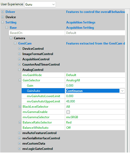
In ImpactControlCenter just select in "Gain Auto" (AGC) "Continuous". Afterwards, you have the possibility to set minimum and maximum limit combined with AOI setting:
Color Transformation Control
The "Color Transformation Control" contains features like
| Feature name (acc. to SFNC) | Property name (acc. to Impact Acquire) | Description |
| ColorTransformationSelector | colorTransformationEnable | Activates the selected color transformation module. |
| ColorTransformationSelector | colorTransformationSelector | Selects which color transformation module is controlled by the various color transformation features. |
| ColorTransformationValue | colorTransformationValue | Represents the value of the selected Gain factor or Offset inside the transformation matrix. |
| ColorTransformationValueSelector | colorTransformationValueSelector | Selects the gain factor or Offset of the Transformation matrix to access in the selected color transformation module. |
related to the control of the color transformation.
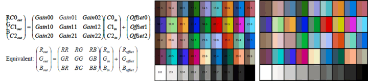
This control offers an enhanced color processing for optimum color fidelity using a color correction matrix (CCM) and enables
- 9 coefficients values (Gain 00 .. Gain 22) and
- 3 offset values (Offset 0 .. Offset 2)
to be entered for RGBIN → RGBOUT transformation. This can be used to optimize specific colors or specific color temperatures.
Coefficients will be made available for sensor models and special requirements on demand.
Event Control
The "Event Control" contains features like
| Feature name (acc. to SFNC) | Property name (acc. to Impact Acquire) | Description |
| EventSelector | eventSelector | Selects which Event to signal to the host application. |
| EventNotification[EventSelector] | eventNotification | Activate or deactivate the notification to the host application of the occurrence of the selected Event. |
| EventFrameTriggerData | eventFrameTriggerData | Category that contains all the data features related to the FrameTrigger event. |
| EventFrameTrigger | eventFrameTrigger | Returns the unique identifier of the FrameTrigger type of event. |
| EventFrameTriggerTimestamp | eventFrameTriggerTimestamp | Returns the timestamp of the AcquisitionTrigger event. |
| EventFrameTriggerFrameID | eventFrameTriggerFrameID | Returns the unique identifier of the frame (or image) that generated the FrameTrigger event. |
| EventExposureEndData | eventExposureEndData | Category that contains all the data features related to the ExposureEnd event. |
| EventExposureEnd | eventExposureEnd | Returns the unique identifier of the ExposureEnd type of event. |
| EventExposureEndTimestamp | eventExposureEndTimestamp | Returns the timestamp of the ExposureEnd Event. |
| EventExposureEndFrameID | eventExposureEndFrameID | Returns the unique identifier of the frame (or image) that generated the ExposureEnd event. |
| EventErrorData | eventErrorData | Category that contains all the data features related to the error event. |
| EventError | eventError | Returns the unique identifier of the error type of event. |
| EventErrorTimestamp | eventErrorTimestamp | Returns the timestamp of the error event. |
| EventErrorFrameID | eventErrorFrameID | If applicable, returns the unique identifier of the frame (or image) that generated the error event. |
| EventErrorCode | eventErrorCode | Returns an error code for the error(s) that happened. |
| etc. |
related to the generation of Event notifications by the device.
The use case Working with Event Control shows how this control can be used.
Chunk Data Control
The "Chunk Data Control" contains features like
| Feature name (acc. to SFNC) | Property name (acc. to Impact Acquire) | Description |
| ChunkModeActive | chunkModeActive | Activates the inclusion of chunk data in the payload of the image. |
| ChunkSelector | chunkSelector | Selects which chunk to enable or control. |
| ChunkEnable[ChunkSelector] | chunkEnable | Enables the inclusion of the selected chunk data in the payload of the image. |
| ChunkImage | chunkImage | Returns the entire image data included in the payload. |
| ChunkOffsetX | ChunkOffsetX | Returns the offset x of the image included in the payload. |
| ChunkOffsetY | chunkOffsetY | Returns the offset y of the image included in the payload. |
| ChunkWidth | chunkWidth | Returns the width of the image included in the payload. |
| ChunkHeight | chunkHeight | Returns the height of the image included in the payload. |
| ChunkPixelFormat | chunkPixelFormat | Returns the pixel format of the image included in the payload. |
| ChunkTimestamp | chunkTimestamp | Returns the timestamp of the image included in the payload at the time of the FrameStart internal event. |
| etc. |
related to the Chunk Data Control.
Possible chunk data:
- Image
- OffsetX
- OffsetY
- Width
- Height
- PixelFormat
- Timestamp
- LineStatusAll
- CounterValue
- TimerValue
- ExposureTime
- SequencerSetActive
- Gain
- mvCustomerIdentifier
A description can be found in the image acquisition section of the Impact Acquire API manuals.
File Access Control
The "File Access Control" contains features like
| Feature name (acc. to SFNC) | Property name (acc. to Impact Acquire) | Description |
| FileSelector | fileSelector | Selects the target file in the device. |
| FileOperationSelector[FileSelector] | fileOperationSelector | Selects the target operation for the selected file in the device. |
| FileOperationExecute[FileSelector][FileOperationSelector] | fileOperationExecute | Executes the operation selected by FileOperationSelector on the selected file. |
| FileOpenMode[FileSelector] | fileOpenMode | Selects the access mode in which a file is opened in the device. |
| FileAccessBuffer | fileAccessBuffer | Defines the intermediate access buffer that allows the exchange. |
| etc. |
related to the File Access Control that provides all the services necessary for generic file access of a device.
Digital I/O Control
The "Digital I/O Control" contains features like
| Feature name (acc. to SFNC) | Property name (acc. to Impact Acquire) | Description |
| LineSelector | lineSelector | Selects the physical line (or pin) of the external device connector to configure. |
| LineMode[LineSelector] | lineMode | Controls if the physical Line is used to Input or Output a signal. |
| UserOutputSelector | userOutputSelector | Selects which bit of the user output register will be set by UserOutputValue. |
| UserOutputValue[UserOutputSelector] | userOutputValue | Sets the value of the bit selected by UserOutputSelector. |
| etc. |
related to the control of the general input and output pins of the device.
Additionally, Balluff offers:
- mvLineDebounceTimeRisingEdge and
- mvLineDebounceTimeFallingEdge functionality.
A description of these functions can be found in the use case Creating a debouncing filter at the inputs.
How you can test the digital inputs and outputs is described in "Testing The Digital Inputs" in the "Impact Acquire SDK GUI Applications" manual. The use case Creating synchronized acquisitions is a further example which shows you how to work with digital inputs and outputs.
Encoder Control
The "Encoder Control" contains features like
| Feature name (acc. to SFNC) | Property name (acc. to Impact Acquire) | Description |
| EncoderSourceA | encoderSourceA | Selection of the A input line. |
| EncoderSourceB | encoderSourceB | Selection of the B input line. |
| EncoderMode [FourPhase] | encoderMode | The counter increments or decrements 1 for every full quadrature cycle. |
| EncoderDivider | encoderDivider | Sets how many Encoder increment/decrements that are needed generate an encoder output signal. |
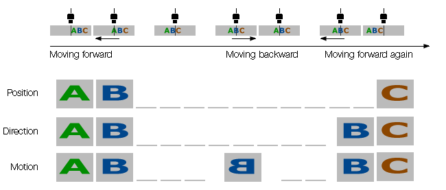
| EncoderOutputMode | encoderOutputMode | Output signals are generated at all new positions in one direction. If the encoder reverses no output pulse are generated until it has again passed the position where the reversal started. |
| EncoderValue | encoderValue | Reads or writes the current value of the position counter of the selected Encoder. Writing to EncoderValue is typically used to set the start value of the position counter. |
related to the usage if quadrature encoders.
The following figure explains the different EncoderOutputModes :
Additionally, the Encoder is also available as TriggerSource and as an EventSource.
A description of incremental encoder's principle can be found in the use case Processing triggers from an incremental encoder.
Transport Layer Control
The "Transport Layer Control" contains features like
| Feature name (acc. to SFNC) | Property name (acc. to Impact Acquire) | Description |
| PayloadSize | payloadSize | Provides the number of bytes transferred for each image or chunk on the stream channel. |
| GevInterfaceSelector | gevInterfaceSelector | Selects which physical network interface to control. |
| GevMACAddress[GevInterfaceSelector] | gevMACAddress | MAC address of the network interface. |
| GevStreamChannelSelector | gevStreamChannelSelector | Selects the stream channel to control. |
| PtpControl | ptpEnable | Enables the Precision Time Protocol (PTP). |
| etc. |
related to the Transport Layer Control.
Use cases related to the "Transport Layer Control" are:
User Set Control
The "User Set Control" contains features like
| Feature name (acc. to SFNC) | Property name (acc. to Impact Acquire) | Description |
| UserSetSelector | userSetSelector | Selects the feature user set to load, save or configure. |
| UserSetLoad[UserSetSelector] | userSetLoad | Loads the user set specified by UserSetSelector to the device and makes it active. |
| UserSetSave[UserSetSelector] | userSetSave | Endianess of the device registers. |
| UserSetDefault | userSetDefault | Selects the feature user set to load and make active when the device is reset. |
related to the User Set Control to save and load the user device settings.
The camera allows the storage of up to four configuration sets in the camera. This feature is similar to storing settings in the registry but this way in the camera. It is possible to store
- exposure,
- gain,
- AOI,
- frame rate,
- etc.
permanently. You can select, which user set comes up after hard reset.
Use case related to the "User Set Control" is:
Another way to create user data is described here: Creating user data entries
Action Control
The "Action Control" contains features like
| Feature name (acc. to SFNC) | Property name (acc. to Impact Acquire) | Description |
| ActionDeviceKey | actionDeviceKey | Provides the device key that allows the device to check the validity of action commands. The device internal assertion of an action signal is only authorized if the ActionDeviceKey and the action device key value in the protocol message are equal. |
| ActionSelector | actionSelector | Selects to which action signal further action settings apply. |
| ActionGroupKey | actionGroupKey | Provides the key that the device will use to validate the action on reception of the action protocol message. |
| ActionGroupMask | actionGroupMask | Provides the mask that the device will use to validate the action on reception of the action protocol message. |
related to the Action control features.
The use case Using Action Commands shows in detail how this feature works.
mv Serial Interface Control
The "mv Serial Interface Control" contains features like
| Feature name (acc. to SFNC) | Property name (acc. to Impact Acquire) | Description |
| mvSerialInterfaceMode | States the interface mode of the serial interface. | |
| mvSerialInterfaceEnable | Controls whether the serial interface is enabled or not. | |
| mvSerialInterfaceBaudRate | Serial interface clock frequency. | |
| mvSerialInterfaceASCIIBuffer | Buffer for exchanging ASCII data over serial interface. | |
| mvSerialInterfaceWrite | Command to write data from the serial interface. | |
| mvSerialInterfaceRead | Command to read data from the serial interface. | |
| etc. |
related to control the devices Serial Interface Control parameters. It enables the camera to be controlled via serial interface.
The use case Working With The Serial Interface (mv Serial Interface Control) shows how you can work with the serial interface control.
With the Serial Interface Control the optional fan in Working with the temperature sensors is controlled.
mv Auto Feature Control
The "mv Auto Feature Control" contains features like
| Feature name (acc. to SFNC) | Property name (acc. to Impact Acquire) | Description |
| mvAutoFeatureAOIMode | Common AutoControl AOI used for Auto Gain Control(AGC), Auto Exposure Control(AEC) and Auto White Balancing. | |
| mvAutoFeatureSensitivity | The controllers sensitivity of brightness deviations. This parameter influences the gain as well as the exposure controller. | |
| mvAutoFeatureCharacteristic | Selects the prioritization between Auto Exposure Control(AEC) and Auto Gain Control(AGC) controller. | |
| mvAutoFeatureBrightnessTolerance | The error input hysteresis width of the controller. If the brightness error exceeds the half of the value in positive or negative direction, the controller restarts to control the brightness. |
related to the automatic control of exposure, gain, and white balance.
With this control you can influence the characteristic of the controller depending on certain light situations. AEC/AGC can be controlled with the new additional properties mvAutoFeatureSensitivity, mvAutoFeatureCharacteristic and mvAutoFeatureBrightnessTolerance.