Loading...
Searching...
No Matches
Creating synchronized acquisitions
Introduction
Getting images from several cameras exactly at the same time is a major task in
- 3D image acquisitions
(the images must be acquired at the same time using two cameras) or - acquisitions of larger objects
(if more than one camera is required to span over the complete image, like in the textile and printing industry).
With Balluff/MATRIX VISION cameras you can solve this task as follows:
- Using Action Commands
- It is not certain that the cameras acquire the images at exactly the same time.
- The host application has to actively pull the trigger.
- Using timers
- Using mvCyclicSignal (via IEEE1588)
Using timers
Timers can be used to generate pulses at regular intervals. These pulses can be connected to a digital output. The digital output can be connected again to the digital input of one or more cameras to use it as a trigger.
Connecting the hardware
- Note
- We recommend to use the cable "KS-BCX-HR12" to connect an external power supply (at pin 2 and 10) and the I/Os.
On the master camera
- Connect power supply GND to "pin 1" and "pin 7".
- Connect power supply +12 V to "pin 2" and "pin 10 (power supply for the outputs)".
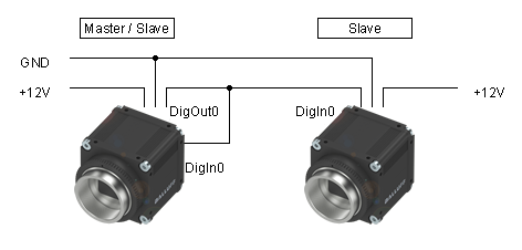
- Connect DigOut0 of master ("pin 6") to DigIn0 of master ("pin 4").
On each slave camera
- Connect power supply GND to "pin 1" and "pin 7".
- Connect power supply +12 V to "pin 2" and "pin 10 (power supply for the outputs)".
Between the cameras
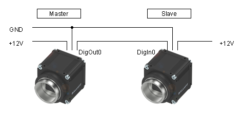
- Connect DigOut0 of master ("pin 6") to DigIn0 of slave ("pin 4").
- Note
- If more than one slave is used, connect the same "pin 6" of master to all "pin 4" of the slaves.
- If each camera has its own power supply, then connect all grounds (GND) together.
For the master camera, there are 2 possibilities how it is triggered:
- The master camera triggers itself logically (so called "Master - Slave", see Figure 1), or
- the master camera uses the external trigger signal, which was created by itself, via digital input (so called "Slave - Slave", see Figure 2).
- Note
- With "Master - Slave" and according to the delay of the opto-isolated inputs of the slave cameras, you have to adapted the property "Trigger delay" of the master camera to synchronize the cameras exactly.
Programming the acquisition
You will need two timers and you have to set a trigger.
Start timer
Two timers are used for the "start timer". Timer1 defines the interval between two triggers. Timer2 generates the trigger pulse at the end of Timer1.
The following sample shows a trigger
- which is generated every second and
- the pulse width is 10 ms:
#include <mvIMPACT_CPP/mvIMPACT_acquire.h>
#include <mvIMPACT_CPP/mvIMPACT_acquire_GenICam.h>

...

// Master: Set timers to trig image: Start after queue is filled
    GenICam::CounterAndTimerControl catcMaster(pDev);
    catcMaster.timerSelector.writeS( "Timer1" );
    catcMaster.timerDelay.write( 0. );
    catcMaster.timerDuration.write( 1000000. );
    catcMaster.timerTriggerSource.writeS( "Timer1End" );

    catcMaster.timerSelector.writeS( "Timer2" );
    catcMaster.timerDelay.write( 0. );
    catcMaster.timerDuration.write( 10000. );
    catcMaster.timerTriggerSource.writeS( "Timer1End" );
- See also
- Counter And Timer Control
- Note
- Make sure the Timer1 interval must be larger than the processing time. Otherwise, the images are lost.
The timers are defined, now you have to do following steps:
- Set the digital output, e.g. "Line 0" ,
- connect the digital output with the inputs of the slave cameras (and master camera if using "Slave - Slave"), and finally
- set the trigger source to the digital input, e.g. "Line4".
Set digital I/O
In this step, the signal has to be connected to the digital output, e.g. "Line0":
// Set Digital I/O
    GenICam::DigitalIOControl io(pDev);
    io.lineSelector.writeS( "Line0" );
    io.lineSource.writeS( "Timer2Active" );
- See also
- Digital I/O Control
This signal has to be connected with the digital inputs of the slave cameras as shown in Figure 1 and 2.
Set trigger
"If you want to use Master - Slave":
// Set Trigger of Master camera
    GenICam::AcquisitionControl ac(pDev);
    ac.triggerSelector.writeS( "FrameStart" );
    ac.triggerMode.writeS( "On" );
    ac.triggerSource.writeS( "Timer1Start" );
// or ac.triggerSource.writeS( "Timer1End" );
// Set Trigger of Slave camera
    GenICam::AcquisitionControl ac(pDev);
    ac.triggerSelector.writeS( "FrameStart" );
    ac.triggerMode.writeS( "On" );
    ac.triggerSource.writeS( "Line4" );
    ac.triggerActivation.writeS( "RisingEdge" );
"If you want to use Slave - Slave":
// Set Trigger of Master and Slave camera
    GenICam::AcquisitionControl ac(pDev);
    ac.triggerSelector.writeS( "FrameStart" );
    ac.triggerMode.writeS( "On" );
    ac.triggerSource.writeS( "Line4" );
    ac.triggerActivation.writeS( "RisingEdge" );
- See also
- Acquisition Control
Now, the two timers will work like the following figure illustrates, which means
- Timer1 is the trigger event and
- Timer2 the trigger pulse width:
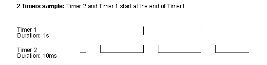
By the way, this is a simple "pulse width modulation (PWM)" example.
Setting the synchronized acquisition using ImpactControlCenter
The following figures show, how you can set the timers and trigger using the GUI tool ImpactControlCenter
-
Setting of Timer1 (blue box) on the master camera:
Figure 4: ImpactControlCenter - Setting of Timer1 on the master camera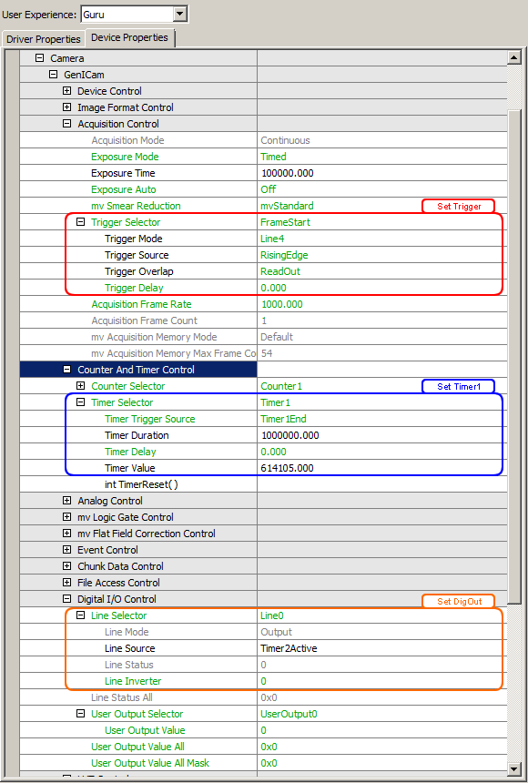
-
Setting of Timer2 (purple box) on the master camera:
Figure 5: ImpactControlCenter - Setting of Timer2 on the master camera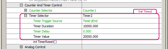
-
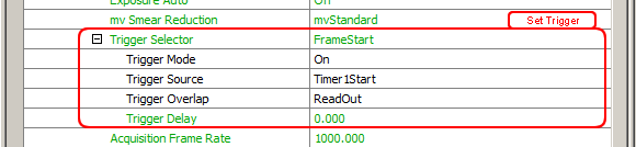
Setting the trigger slave camera(s)
- The red box in Figure 4 is showing "Slave - Slave", which means that both master and slave camera are connected via digital input.
- The red box in Figure 6 is showing "Master - Slave"), which means that the master is triggered internally and the slave camera is set as shown in Figure 4. - Assigning timer to DigOut (orange box in Figure 4).
Using mvCyclicSignal (via IEEE1588)
The mvCyclicSignal makes it possible synchronizing image captures of all cameras without extra cabling and without steady image triggering from an application. For this the cameras in the system need to have synchronized clocks using the IEEE1588 feature.
- Note
- This way of synchronization still faces the usual precision limits of the cameras caused by the used sensors. This is a certain latency and jitter of the internally generated trigger (which is of high precision) to the actual
ExposureStart. This latency and jitter are sensor and operating mode specific.
Setting the mvCyclicSignal using ImpactControlCenter
The mvCyclicSignal can be found in "Setting → Base → Camera → GenICam → mvCyclicSignalControl".
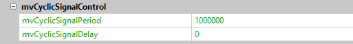
mvCyclicSignal provides two further properties:
mvCyclicSignalPeriod
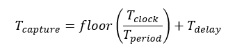
The frame period is used for synchronization of the image acquisition additionally to the clock time. I.e. when the time is divisble by the period without any rest, the acquisition is going to start. In this case, it doesn’t matter, when the cameras are initialized, they all would lock to the same points in time, if the period is the same.mvCyclicSignalDelay
This property allows to start the acquisition after an additional delay and not only at times which are divisible by the period. I.e. images would be acquired at clock times divisible by the period without rest plus the delay.
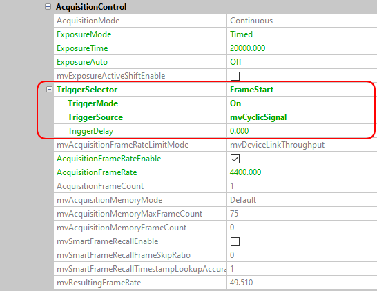
In the TriggerSelector section of the AcquisitionControl it is necessary to activate the mvCyclicSignal:
-
In "Setting → Base → Camera → GenICam → AcquisitionControl" select mvCyclicSignal as
TriggerSource. -
Activate the trigger by setting the
TriggerModeto On.
Example 1: mvCyclicSignalPeriod
Setting the mvCyclicSignalPeriod to 10 minutes and having 2 cameras,
- Camera A (initialized at 12:05) and
- Camera B (initialized at at 12:35)
The acquisitions would be as follows:
Camera A: 12:10, 12:20, 12:30, 12:40, 12:50, 13:00, etc.
Camera B:                      12:40, 12:50, 13:00, etc.
The first image of Camera B would be synchronized with Camera A. As long as the cameras clocks are synced by IEEE1588, they will be synchronized with very good precision.
Example 2: mvCyclicSignalDelay
With the same mvCyclicSignalPeriod as in example 1, the following mvCyclicSignalDelay is added in each case:
- Camera A: 2 min
- Camera B: 6 min
The acquisitions would be as follows:
Camera A: 12:12, 12:22, 12:32, 12:42, 12:52, 13:02, etc.
Camera B:               12:36, 12:46, 12:56, 13:06, etc.
Cameras A and B are still synchronized, but with a phase delay between them of 4 minutes (6 minutes – 2 minutes).