Loading...
Searching...
No Matches
Generating a pulse width modulation (PWM)
Introduction
To dim a laser line generator, for example, you have to generate a pulse width modulation (PWM).
For this, you will need
- 2 timers and
- the active signal of the second timer at an output line
Using ImpactControlCenter
The following figures show, how you can set the timers using the GUI tool ImpactControlCenter
-
Setting of Timer1 (blue box) on the master camera:
Figure 1: ImpactControlCenter - Setting of Timer1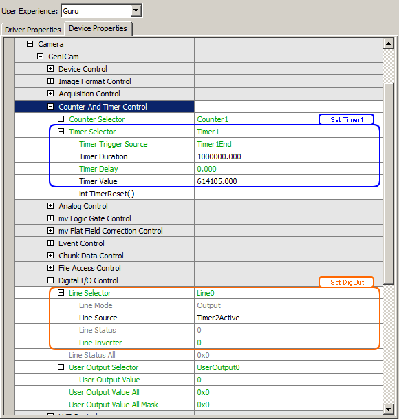
-
Setting of Timer2 (purple on the master camera):
Figure 2: ImpactControlCenter - Setting of Timer2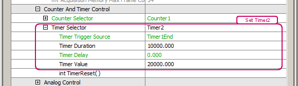
- Assigning timer to DigOut (orange box in Figure 2).
Programming the pulse width modulation
You will need two timers and you have to set a trigger.
- Timer1 defines the interval between two triggers.
- Timer2 generates the trigger pulse at the end of Timer1.
The following sample shows a trigger
- which is generated every second and
- the pulse width is 10 ms:
#include <mvIMPACT_CPP/mvIMPACT_acquire.h>
#include <mvIMPACT_CPP/mvIMPACT_acquire_GenICam.h>

...

// Master: Set timers to trig image: Start after queue is filled
    GenICam::CounterAndTimerControl catcMaster(pDev);
    catcMaster.timerSelector.writeS( "Timer1" );
    catcMaster.timerDelay.write( 0. );
    catcMaster.timerDuration.write( 1000000. );
    catcMaster.timerTriggerSource.writeS( "Timer1End" );

    catcMaster.timerSelector.writeS( "Timer2" );
    catcMaster.timerDelay.write( 0. );
    catcMaster.timerDuration.write( 10000. );
    catcMaster.timerTriggerSource.writeS( "Timer1End" );
- See also
- Counter And Timer Control
- Note
- Make sure the Timer1 interval must be larger than the processing time. Otherwise, the images are lost.
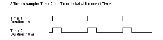
Now, the two timers will work like the following figure illustrates, which means
- Timer1 is the trigger event and
- Timer2 the trigger pulse width:
The timers are defined, now you have to set the digital output, e.g. "Line 0":
// Set Digital I/O
    GenICam::DigitalIOControl io(pDev);
    io.lineSelector.writeS( "Line0" );
    io.lineSource.writeS( "Timer2Active" );
- See also
- Digital I/O Control
This signal has to be connected with the digital inputs of the application.