Defective Pixel Correction
Due to random process deviations, technical limitations of the sensors, etc. there are different reasons that image sensors have image errors. Balluff provides several procedures to correct these errors, by default these are host-based calculations, however some device families support device-based corrections, which saves dozens of % CPU load and lowers latency.
| Device Family BVS CA- | Adaptive defective pixel correction (Device) | List-based defective pixel correction (Device) | List-based defective pixel correction (Host) | Flat-Field Correction (Host) | Flat-Field Correction (Device) |
| GX0 | - | - | X | X | X |
| GX2 | X* | X | X | X | - |
| GT1 | X** | - | X | X | - |
| SF1 | - | - | X | X | - |
| SF2..SF5 | X* | X | X | X | - |
| IGC/MLC | - | - | X | X | - |
* Applies when binning/decimation is used; mvDevicePixelEnable enabled.
** Always active
There are exceptions. In doubt check the Appendix A. Specific Camera / Sensor Data .
Generally, removing defect pixels requires two sub-tasks:
- Detection of defective pixels
- Correction of defective pixels
Both tasks can performed in different "locations":
- Detection and correction on the host using Impact Acquire
- Detection on the host using Impact Acquire, correction on the device using the device's
mvDefectivePixelCorrectionControlin the list-based mode - Detection and correction on the camera using
mvDefectivePixelCorrectionControlin the algorithm-based mode.
If detection is not happening in real-time, meaning during the image acquisition itself, it is necessary to store the detected defects somewhere. This can be either on the device or the host or both.
Host-based defect pixel detection
As mentioned, the defect pixel list can be generated using Impact Acquire. Since there are three types of defects, Impact Acquire offers three calibration methods for detection:
-
leaky pixel (in the dark)
which indicates pixels that produce a higher read out code than the average -
hot pixel (in standard light conditions)
which indicates pixels that produce a higher non-proportional read out code when temperatures are rising -
cold pixel (in standard light conditions)
which indicates pixels that produce a lower read out code than average when the sensor is exposed (e.g. caused by dust particles on the sensor)
- Note
- Please use either an Mono or RAW Bayer image format when detecting defective pixel data in the image.
Detecting leaky pixels
To detect leaky pixels the following steps are necessary:
-
Set gain (
"Setting → Base → Camera → GenICam → Analog Control → Gain = 0 dB") and exposure time"Setting → Base → Camera → GenICam → Acquisition Control → ExposureTime = 360 msec"to the given operating conditions
The total number of defective pixels found in the array depend on the gain and the exposure time. - Black out the lens completely
-
Set the (Filter-)
"Mode = Calibrate leaky pixel" -
Acquire an image (e.g. by pressing Acquire in ImpactControlCenter with
"Acquisition Mode = SingleFrame")
The filter checks:
Pixel > LeakyPixelDeviation_ADCLimit
All pixels above this value are considered as leaky pixel.
- Note
- The allowed range of the
LeakyPixelDeviation_ADCLimitproperty is 0 - 255 (with a default value of 50) for historical reasons. So originally it was meant to be used for 8-bit formats. The value however will be standardized matching the corresponding pixel format automatically during the calibration process, so e.g. setting it to 128 will result in 128 to be used for 8-bit format, 512 for 10-bit formats, 2048 for 12-bit formats and so on.
Detecting hot or cold pixels
- Note
- With "Mode = Calibrate Hot And Cold Pixel" you can execute both detections at the same time.
To detect hot or cold pixels the following steps are necessary:
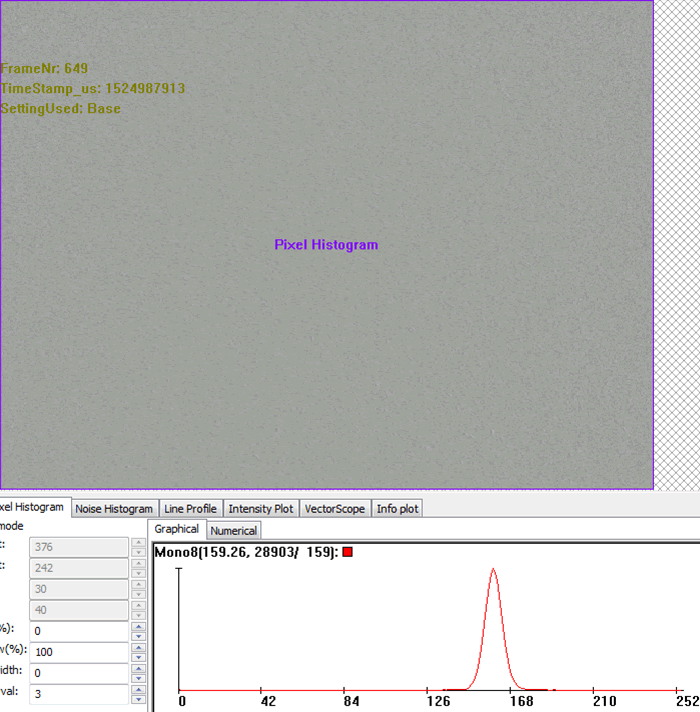
- You will need a uniform sensor illumination approx. 50 - 70 % saturation (which means an average gray value between 128 and 180)
-
Set the (Filter-)
"Mode = Calibrate Hot Pixel"or"Mode = Calibrate Cold Pixel"or"Mode = Calibrate Hot And Cold Pixel" -
Acquire an image (e.g. by pressing Acquire in ImpactControlCenter with
"Acquisition Mode = SingleFrame")
The filter checks:
Pixel > T[hot] // (default value: 15 %)

// T[hot] = deviation of the average gray value
Pixel < T[cold] // (default value: 15 %)

// T[cold] = deviation of the average gray value
- Note
- Repeating the defective pixel corrections will accumulate the correction data which leads to a higher value in
"DefectivePixelsFound". If you want to reset the correction data or repeat the correction process you have to set the filter mode to"Reset Calibration Data". In order to limit the amount of defective pixels detected the"DefectivePixelsMaxDetectionCount"property can be used.
Storing defective pixel data on the device
To save and load the defective pixel data, appropriate functions are available:
- "int mvDefectivePixelDataLoad( void )"
- "int mvDefectivePixelDataSave( void )"
The section "Setting → Base → ImageProcessing → DefectivePixelsFilter" was also extended (see Figure 2). First, the "DefectivePixelsFound" indicates the number of found defective pixels. The coordinates are available through the properties "DefectivePixelOffsetX" and "DefectivePixelOffsetY" now. In addition to that it is possible to edit, add and delete these values manually (via right-click on the "DefectivePixelOffset" and select "Append Value" or "Delete Last Value"). Second, with the functions
- "int mvDefectivePixelReadFromDevice( void )"
- "int mvDefectivePixelWriteToDevice( void )"
you can exchange the data from the filter with the device and vice versa.
Just right-click on "mvDefectivePixelWriteToDevice" and click on "Execute" to write the data to the device (and hand over the data to the Storing pixel data on the device). To permanently store the data inside the device s non-volatile memory afterwards "mvDefectivePixelDataSave" must be called as well!
While opening the device, the device will load the defective pixel data from the device. If there are pixels in the filter available (via calibration), nevertheless you can load the values from the device. In this case the values will be merged with the existing ones. I.e., new ones are added and duplicates are removed.
Host-based defect pixel correction
After a defect-list is generated, a host-based correction can be performed using Impact Acquire.
To correct the defective pixels various substitution methods exist:
-
"Replace 3x1 average"
which substitutes the detected defective pixels with the average value from the left and right neighboring pixel (3x1) -
"Replace 3x3 median"
which substitutes the detected defective pixels with the median value calculated from the nearest neighboring in a 3 by 3 region -
"Replace 3x3 Filtered Data Averaged"
which substitutes and treats the detected defective pixels as if they have been processed with a 3 by 3 filter algorithm before reaching this filter
Only recommended for devices which do not offer a defective pixel compensation; packed RGB or packed YUV444 data is needed. See enumeration valuedpfmReplaceDefectivePixelAfter3x3Filterin the corresponding API manual for additional details about this algorithm and when and why it is needed
List-based defect pixel correction on the device
As described before, it is possible to upload lists of defect pixel onto the device. Different algorithms can be used to determine whether a pixel is defective or not, which is dependent of how much it is allowed a pixel to deviate, temperature, gain, and exposure time. As described before, the list-based correction is deterministic, meaning it is exactly known which pixels will be corrected.
Anyhow, the list-based correction has some disadvantages:
- A default list is stored in the device during production, but this might to fit to the target application because of much different temperature / exposure time setting
→ It is necessary to create the list using a detection algorithm (or Impact Acquire support) - During time and sensor aging, new defects could/will appear
- It doesn’t work in binning/decimation modes
- The memory for storing defective pixels is limited
Adaptive / algorithm-based correction on the device
In this case, the device performs detection and correction on-the-fly without using any defect-list.
The adaptive correction addresses the above-mentioned disadvantages of the list-based method. While the correction itself (this is which pixels are used to correct an identified defect) is the same, no static information from a list is used, instead they are detected "on the fly".
To use reasonable thresholds, knowledge of the noise statistics of the sensor is used to detect the outliers. These will be corrected also on the fly. Because this is a dynamic approach, it also works in binning/decimation modes and would also detect new appearing defects.
Nevertheless, there are some disadvantages:
- It is non-deterministic
- Wrong positives can be detected, meaning non-defect pixels could be treated as defect
If pixels are at the edge of the used thresholds, it could be corrected in one frame, but not in the next
On BVS CA-SF devices, the adaptive correction is always used if:
- There is no list stored on the device
- Binning or decimation is used
Flat-Field Correction
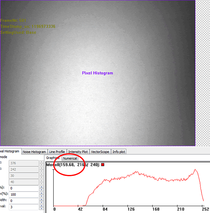
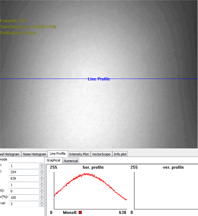
Each pixel of a sensor chip is a single detector with its own properties. Particularly, this pertains to the sensitivity as the case may be the spectral sensitivity. To solve this problem (including lens and illumination variations), a plain and equally "colored" calibration plate (e.g. white or gray) as a flat-field is snapped, which will be used to correct the original image. Between flat-field correction and the future application you must not change the optic. To reduce errors while doing the flat-field correction, a saturation between 50 % and 75 % of the flat-field in the histogram is convenient.
- Note
- Flat-field correction can also be used as a destructive watermark and works for all f-stops.
To make a flat field correction following steps are necessary:
- You need a plain and equally "colored" calibration plate (e.g. white or gray)
- No single pixel may be saturated - that's why we recommend to set the maximum gray level in the brightest area to max. 75% of the gray scale (i.e., to gray values below 190 when using 8-bit values)
-
Choose a
BayerXYin "Setting → Base → Camera → GenICam → Image Format Control → PixelFormat". -
Set the (Filter-)
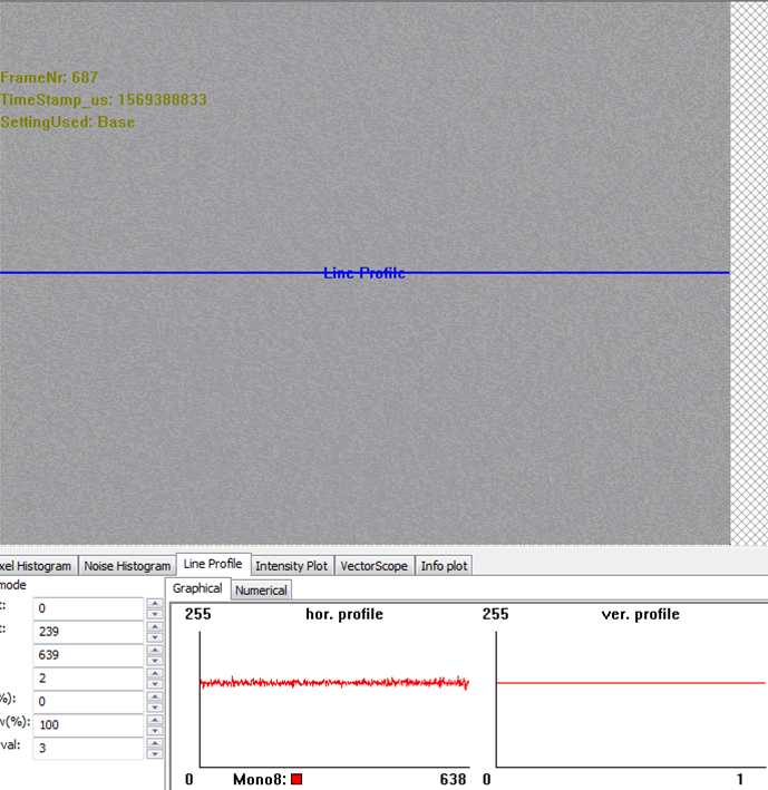
"Mode = Calibrate"(Figure 4) -
Start a Live snap ("Acquire" with
"Acquisition Mode = Continuous") -
Finally, you have to activate the correction: Set the (Filter-)
"Mode = On" -
Save the settings including the correction data via
"Action → Capture Settings → Save Active Device Settings"
(Settings can be saved in the Windows® registry or in a file)
- Note
- After having re-started the device you have to reload the capture settings vice versa.
The filter snaps a number of images (according to the value of the CalibrationImageCount, e.g. 5) and averages the flat-field images to one correction image.

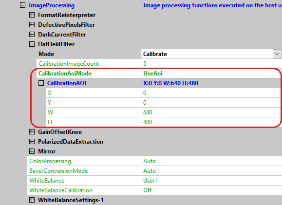
Host-based Flat-Field Correction With Calibration AOI
In some cases it might be necessary to use just a specific area within the device's field of view to calculate the correction values. In this case just a specific AOI will be used to calculate the correction factor.
You can set the "host-based flat field correction" in the following way:
- All necessary setting can be found under "ImageProcessing"-> "FlatfieldFilter".
- Stop "Continuous" acquisition mode.
- Set "CalibrationImageCount" to, for example, 5.
- Set "Mode" to "Calibrate".
- Set "CalibrationAoiMode" to "UseAoi".
- Set the properties ("X, Y and W, H") appeared under "CalibrationAOI" to the desired AOI.
- Start "Continuous" acquisition mode.
- Finally, you have to activate the correction: Set the "Mode" to "On".
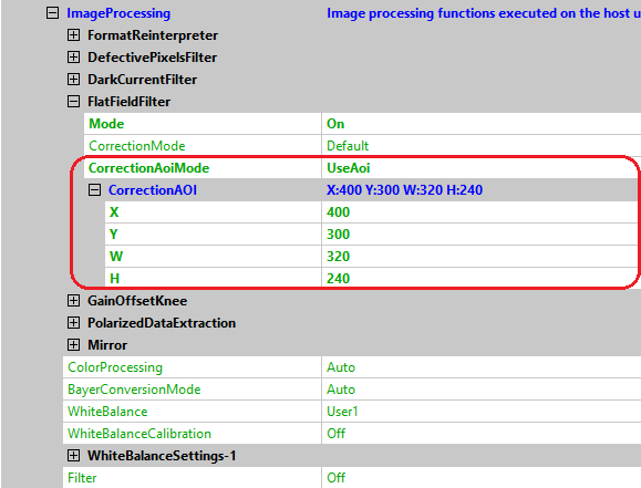
Host-based Flat-Field Correction With Correction AOI
In some cases it might be necessary to correct just a specific area in the device's filed of view. In this case the correction values are only applied to a specific area. For the rest of the image, the correction factor will be just 1.0.
You can set the "host-based flat field correction" in the following way:
- All necessary setting can be found under "ImageProcessing → FlatfieldFilter".
- Stop "Continuous" acquisition mode.
- Set "CalibrationImageCount" to, for example, 5.
- Set "Mode" to "Calibrate".
- Start "Continuous" acquisition mode.
- Now, you have to activate the correction: Set the "Mode" to "On".
- Set "CorrectionAOIMode" to "UseAoi".
- Finally use the properties ("X, Y and W, H") which appeared under "CorrectionAOI" to configure the desired AOI.
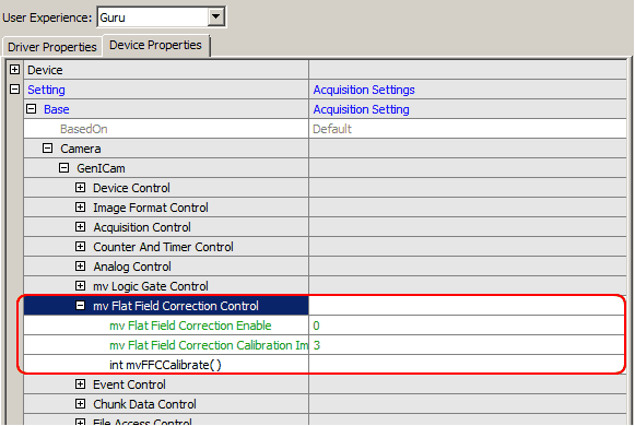
Device-based Flat-Field Correction
The device-based Flat-Field Correction feature supports full AOI and 14 bit to 14 bit correction (12 bit coefficients.). This enables a pixel to pixel correction and saves dozens of % CPU load and lowers latency. To reduce noise averaging of a number of "mv Flat-Field Correction Calibration Images" is possible. A correction image in the device is then calculated. This may take some time / number of images, however, the device blinks green. One correction image can be stored for all user settings.
The device-based Flat-Field Correction is independent of the offset and uses a run-mode trigger (e.g. external trigger).
You can set the "device-based flat field correction" in the following way:
- Set "mv Flat-Field Correction Calibration Image Count" to, for example, 5.
- This will average 5 images before calculating the FFC factors to reduce impact of noise.
- Stop "Continuous" acquisition mode, then right click on "int mvFFCCalibrate()" → "Execute".
-
Finally, you have to activate the correction: Set the
"mv Flat-Field Correction Enable = 1".
Depending on the sensor, this need some time, because the data is stored in the internal flash memory (yellow LED lights up).
Example
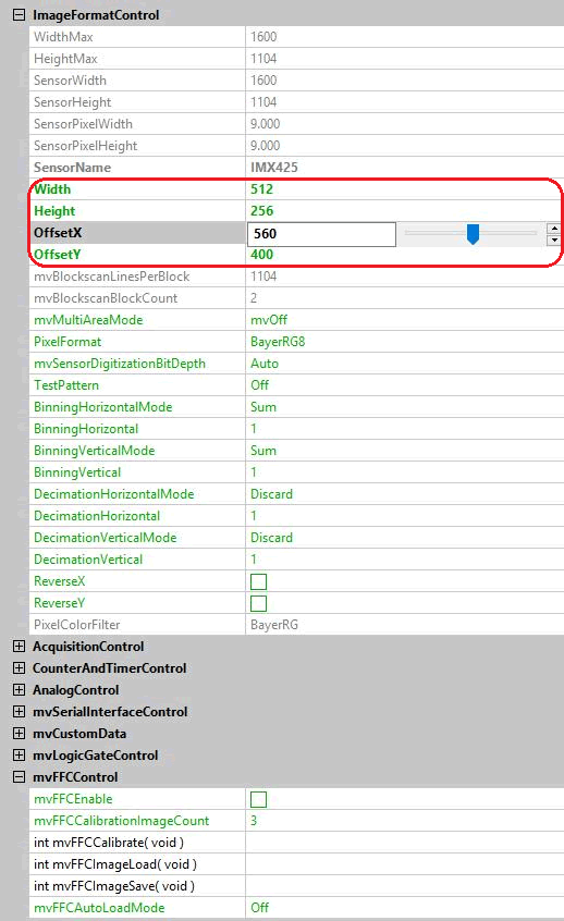
Device-based Flat-Field Correction With Calibration AOI
In some cases it might be necessary to use just a specific area within the device's field of view to calculate the correction values. In this case just a specific AOI will be used to calculate the correction factor.
You can set the "device-based flat field correction with AOI" in the following way:
- Start "Continuous" acquisition mode.
-
Use the properties ("OffsetX, OffsetY and W, H") to configure the desired AOI for FFC calculation.
Stop the acquisition first to change W and H in Image Format Control . Only OffsetX and OffsetY can be changed on the fly. - Set mvFFCCalibrationImageCount to, for example, 5.
- This will average 5 images before calculating the FFC factors to reduce impact of noise.
- If it is not already stopped in step 2, stop "Continuous" acquisition mode, then right click on "int mvFFCCalibrate()" → "Execute".
- Use the properties ("OffsetX, OffsetY and W, H") to setup full picture size or desired AOI.
-
Finally, you have to activate the correction: Set the
"mvFFCEnable = 1".
- Note
- Flat-Field Correction is applied to the whole image.
If FFC is working as expected it is possible to store the FFC calibration values in the device if property mvFFCImageSave is available. Depending on the sensor, this will need some time, because the data is stored in the internal flash memory (yellow LED lights up). The FFC values can then be loaded from flash with the command mvFFCImageLoad. If the values should be loaded every time the device is powered up this could be done by setting "mvFFCAutoLoadMode = On"
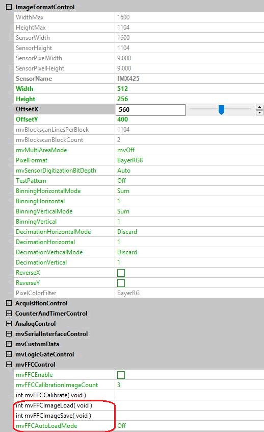
- Note
- Color devices with FW version smaller than 2.40 use a multiplication factor of 1.3 on the correction factor of each color. This factor minimizes color artifacts when the scene gets brighter. Newer Firmware versions use a multiplication factor of 1.0 and to minimize color artifacts use above described AOI method.