Calculating the needed bandwidth
In some applications, for example, when multiple cameras share a single network path, you have to keep the bandwidth in mind.
You can calculate the needed bandwidth with the following formula:
- Note
- Depending on the available link speed different bandwidth are available:
- 10 GBit/s: 1250 MByte/s
- 2 GBit/s: 250 MByte/s
- 1 GBit/s: 125 MByte/s
- 100 MBit/s: 12,5 MByte/s
The result of the formula from above provides a rough guideline only. Some additional bandwidth is needed by the communication protocol and some other non GigE Vision™ related network traffic. Apart from that not every network controller can cope with the full bandwidth offered by the link, thus real world results may vary.
Limiting the bandwidth of the imaging device
For a setup of multiple streaming devices connected to one host, it is highly recommended to consider the information of this chapter.
Even if the connected links and devices are able to handle the average throughput of a streaming setup situations might be encountered where the data throughput temporarily exceeds the capabilities of involved network components for a very short period of time. This might result in packet loss with GigE Vision™ devices or overflowing buffers with USB3 Vision™ devices.
How the Device Link Throughput Limit works
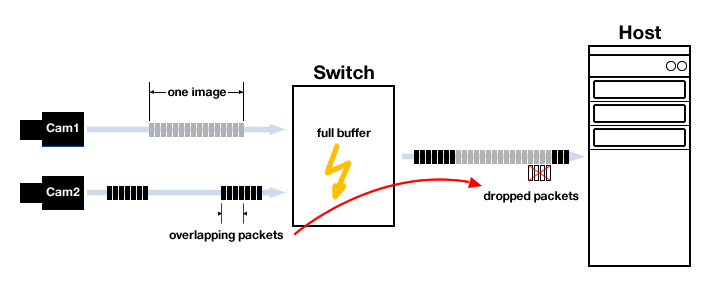
If multiple data packets from multiple network devices arrive at the same time in a switch and therefore the incoming bandwidth temporarily exceeds what the outgoing link can deal with, the switch needs to buffer some of the packets. This is due to the fact, that at full speed, each network packet is sent one after the other, with a minimum space of 12 Bytes between two packets (the so called "inter-packet delay"). That means a data stream will be sent as a series of consecutive packets, separated by the inter-packet delay, until the whole data is transmitted. Since a typical GigE Vision™ streaming network packet is multiple times bigger than a default packet, the switch internal buffer might not be able to store these data for a longer period of time. Consider the following setup:
The GigE Vision™ standard specifies the feature GevSCPD (Stream Channel Packet Delay), so that the user could have control over the link throughput at packet level. The method how the delay is calculated could vary on different device types from different vendors since the unit of the inter-packet delay is measured in device ticks. From version 1.5.2 and above, the GenICam™ SFNC defines the features DeviceLinkThroughputLimit and DeviceLinkThroughputLimitMode, which are meant to provide a standardized way to control the delay by defining a throughput limit rather than an explicit delay.
All Balluff/MATRIX VISION devices support the GenICam™ SFNC features DeviceLinkThroughputLimitMode and DeviceLinkThroughputLimit to limit the bandwidth used by a device in a convenient way since firmware version 2.25.0.
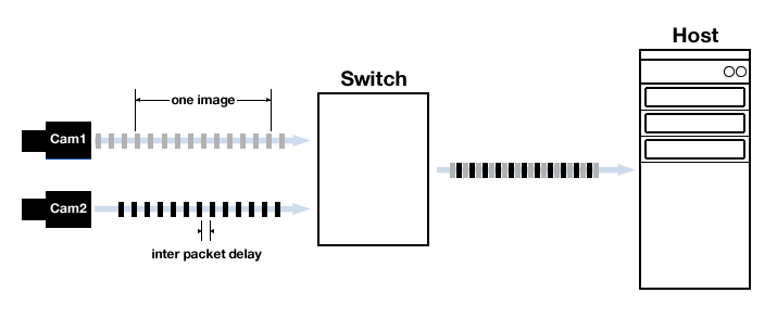
On GigE Vision™ devices, setting the DeviceLinkThroughputLimit results in a longer delay between two consecutive network packets. Now a switch more likely is able to forward all from all incoming links because each link transfers using a reduced data rate, which means less packets need to be buffered reducing the chance for packet loss. However, a larger gap between network packets means, the time to transmit one specific bunch of data could increase. Keep that in mind if you plan an application with hard latency requirements.
If it is necessary to limit the outgoing link throughput of a device, this can be accomplished the following way:
Available since firmware version 2.25.0
-
In
"Setting → Base → Camera → GenICam → Device Control → Device Link Selector"set property "Device Link Throughput Limit Mode" to "On". -
Now, you can set the bandwidth with "Device Link Throughput Limit" to your desired bandwidth in bits per second
ImpactControlCenter - Setting Device Link Throughput Limit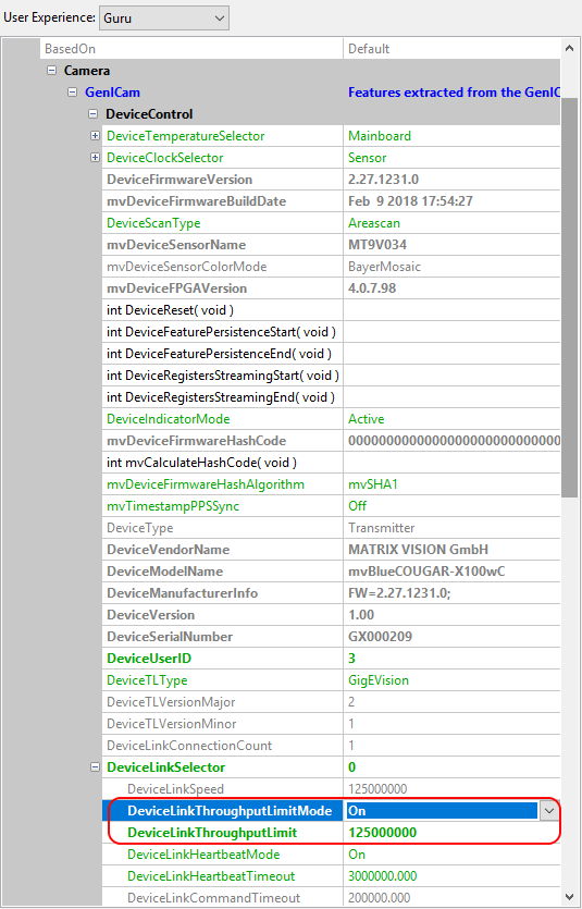
- Note
- Firmware version < 2.25.0
The following features are deprecated and should not be used anymore!
On devices with an older firmware version, limiting the link throughput was done this way.
-
In
"Setting → Base → Camera → GenICam → Transport Layer Control → Gev Stream Channel Selector"set property "mv Gev SCBW Control" to "mvGevSCBW".
ImpactControlCenter - Setting mvGevSCBW to mvGevSCBWControl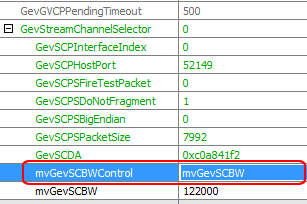
-
Now, you can set the bandwidth with "mvGevSCBW". E.g. 10000 for 10 MB.
According to the image size and acquisition settings, the frame rate will be adjusted.
ImpactControlCenter - Setting bandwidth size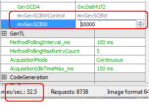
In contrast to this convenient bandwidth control mechanism of BVS CA-GT cameras, with other cameras you have to know and optimize the Inter-Packet Delay of the camera to avoid congestion in the switch (the loss of packages is an indicator of congestion). You can get the Inter-Packet Delay with following calculator: