Introduction
Camera timestamps are a recommended Genicam / SFNC feature to add the information when an image was taken (exactly: when the exposure of the image started).
Without additional synchronization it is merely a camera individual timer with a vendor specific increment and implementation dependent accuracy. Each camera starts its own timestamp beginning with zero and there are no means to adjust or synchronize them among cameras or host PCs. Balluff/MATRIX VISION cameras offer several ways of synchronizing:
The usage is described below.
Without Precision Time Protocol (PTP) IEEE1588
There are many applications which do not or cannot profit from "IEEE1588" but have certain synchronization needs. Solutions for these scenarios are describes as follows.
Synchronizing using mvTimestampReset
First of all the standard does not provide hardware means to reset the timestamp in a camera other than plug off and on again. Therefore Balluff has created its own mechanism mvTimestampReset to reset the timestamp by a hardware input.
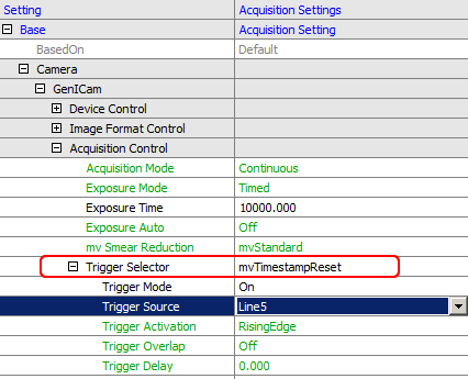
This can be elegantly used for synchronization purposes by means of wiring an input of all cameras together and reset all camera timestamps at the beginning by a defined signal edge from the process. From this reset on all cameras start at zero local time and will increment independently their timestamp so that we achieve a basic accuracy only limited by drift of the clock main frequency (e.g. a 1 MHz oscillator in the FPGA) over time.
In order to compensate for this drift we can in addition reset the timestamp every second or minute or so and count the reset pulse itself by a counter in each camera. Assuming this reset pulse is generated by the master camera itself by means of a timer and output as the hardware reset signal for all cameras, we now can count the reset pulse with all cameras and put both the count and the reset timestamp as so called chunk data in the images.
We thus have achieved a synchronized timestamp with the precision of the master camera among all connected cameras.
Settings required are shown using the ImpactControlCenter tool of Impact Acquire:
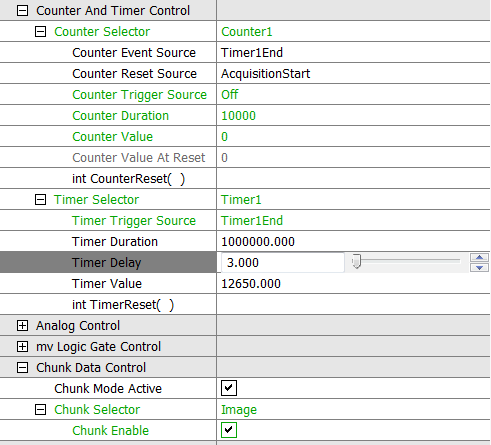
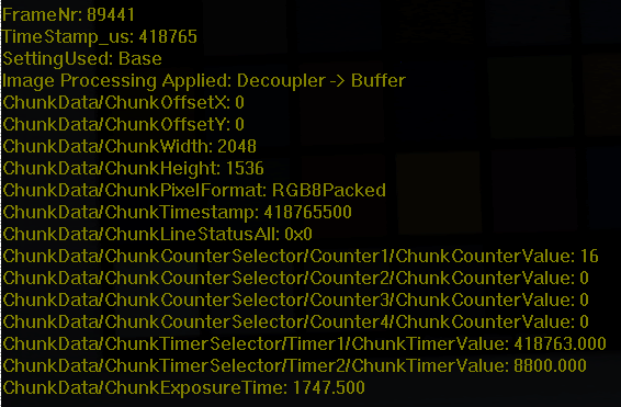
An example of the chunk data attached to the image can be seen below. The timestamp is in µs and Counter1 counts the reset pulses, in this case itself generated by the camera via Timer1.
The task of resetting the counter at the beginning of the acquisition can be done by setting the reset property accordingly. Of course is this all independent whether the camera is acquiring images in triggered or continuous mode.
Synchronizing using a pulse-per-second signal
In order to eliminate the unknown drifts of different devices, a PPS (pulse per second) signal can be fed into each camera using a PC with NTP (network time protocol software), GPS devices or even a looped-back camera timer.
From these pulses the device can extract how long one second is. When a device detects that it is no longer running precisely it will adapt its internal clock leading to a "stabilized oscillator".
The device would then maintain their timestamp-differences over long times and stay synchronized. The initial difference between the timers - before the PPS was used - remains however. If you aim to eliminate that as well, you can use the mvTimestampReset up front with the same PPS input signal. In an application this can be configured like this (C# syntax):
// --------------------------------------------------------------------------
bool waitForNextPulse(Device pDev, String triggerLine)
// --------------------------------------------------------------------------
{
    GenICam.CounterAndTimerControl ctc = new GenICam.CounterAndTimerControl(pDev);
    ctc.counterEventSource.writeS(triggerLine);
    long momentaryValue = ctc.counterValue.read();
    for (int i=0; i<12; i++)
    {
        System.Threading.Thread.Sleep(100);
        if (momentaryValue != ctc.counterValue.read())
        {
            return true;
        }
    }
    return false;
}

// --------------------------------------------------------------------------
void SetupPPS(Device[] pDevs)
// --------------------------------------------------------------------------
{
    string TriggerLine = "Line4";

    if (!waitForNextPulse(pDevs[0],TriggerLine))
    {
        Console.WriteLine("No pulse seems to be present");
        return;
    }

    // No configure all the devices to reset their timestamp with each pulse coming
    // on the trigger line that the PPS signal is connected to.
    foreach(Device aDevice in pDevs)
    {
        GenICam.AcquisitionControl ac = new GenICam.AcquisitionControl(aDevice);
        ac.triggerSelector.writeS("mvTimestampReset");
        ac.triggerSource.writeS(TriggerLine);
        ac.triggerMode.writeS("On");
    }

    // wait for the next pulse that will then reset the timestamps of all the devices
    if (!waitForNextPulse(pDevs[0],TriggerLine))
    {
        Console.WriteLine("the pulses aren't coming fast enough ...");
        return;
    }

    // Now switch off the reset of the timestamp again. All devices did restart their
    // timestamp counters and will stay in sync using the PPS signal now
    foreach(Device aDevice in pDevs)
    {
        GenICam.AcquisitionControl ac = new GenICam.AcquisitionControl(aDevice);
        ac.triggerMode.writeS("Off");
        GenICam.DeviceControl dc = new GenICam.DeviceControl(aDevice);
        dc.mvTimestampPPSSync.writeS("Line4");
    }
}
Using a looped-back camera timer for the PPS signal
To reduce the amount of hardware needed you might want to sacrifice some timestamp validity and use one of the cameras as a master clock. This can be done like this:
- setting Timer1 to duration 1s
- starting Timer2 with every Timer1End and generating a short pulse (duration = 1000 us)
- placing Timer2Active on one of the digital I/O lines and using that as the source for PPS signal
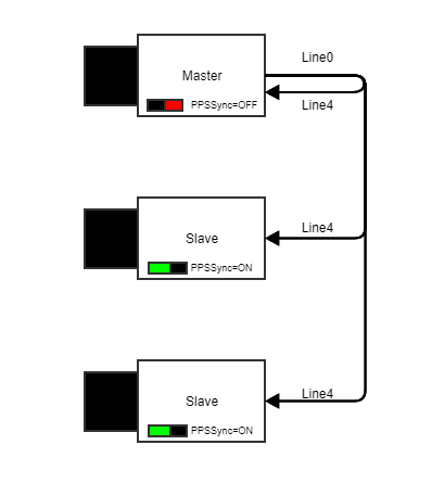
Setting the Timer1 to 1 s seems like an easy task but due to some internal dependencies you should be carefully here. At the moment two different timer implementations are present in Balluff products.
- Type 1: For cameras with sensors other than the IMX family from Sony please set the duration to the theoretical value of 1000000.
- Type 2: For all the other cameras please use 999997 us duration since the self-triggering will consume the other 3 us
- Please refrain from switching on PPSSync inside the Master camera since (at least in Type 1 cameras) since this will lead to an instable feedback loop.
- Note
- For synchronization you can either use PTP or PPS exclusively.
Synchronizing using Precision Time Protocol (PTP) IEEE1588
- Since
- Firmware version 2.37.2285.0
The Precision Time Protocol (PTP) IEEE1588 is a standard for synchronizing devices via Ethernet network. PTP is part of the GigE Vision™ 2.0 standard and offers a microsecond accuracy. We implemented the two-step mode , i.e. the timestamp is sent in a separate message after the sync message. I.e. Balluff/MATRIX VISION cameras are able to perform the required synchronization. However, specific network hardware and Impact Acquire software and procedures can do and maintain the synchronization as well.
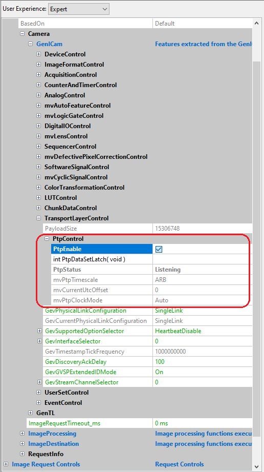
You can get the current state via the PtpDataSetLatch command which will we written in the PtpStatus register.
- Since
- Firmware version 2.57.3849.0
With the property mvPtpClockMode you may select the desired role the camera can assume. By default (Auto), the state of the camera will be selected according to the PTP Protocol, i.e. the device with the best master clock in the network will be the master. All other devices will be slave. When setting mvPtpClockMode to slave, the device can only assume the slave role. Therefore, choose this option only if there is at least one other PTP capable device in the same network, which will then assume the role of the master clock.
The camera status transitions will be as follow (after activating the PTP):
- mvPtpClockMode is set to Auto and no better clock was found: "Disabled → Listening → PreMaster → Master"
- mvPtpClockMode is set to Auto and a better clock was found: "Disabled → Listening → Uncalibrated → Slave"
- mvPtpClockMode is set to Slave and there is a master clock: "Disabled → Listening → Uncalibrated → Slave"
- mvPtpClockMode is set to Slave and there is no master clock: "Disabled → Listening"
For applications, which the used epoch and UTC offset by the master clock may be relevant, Balluff/MATRIX VISION cameras show this information with the registers mvPtpTimescale and mvCurrentUtcOffset respectively. Should a Balluff/MATRIX VISION camera assume the master role after its boot up, mvPtpTimescale will always be Arbitrary (ARB) and mvCurrentUtcOffset always 0. If the device was at any point Slave and then later became master (with no device reset), the camera will keep the values acquired from the old master clock, until a new master with different values is introduced in the network. At this point, the camera will acquire the new values from the new master. The timescales are either PTP or ARB. For more information please refer to the IEEE 1588-2008 specification.
- Note
- With Balluff/MATRIX VISION cameras the mvPtpTimescale and the mvCurrentUtcOffset are merely informative and have no impact whatsoever in the clock synchronization, i.e. the devices will synchronize themselves with the best master clock without applying any offset.
With older versions of Firmware the camera works always as if mvPtpClockMode is set to Auto.
To use the PTP, just activate it like this (mvPtpClockMode can only be changed if PtpEnable is not checked):
-
Check the PtpEnable register in "Setting → Base → Camera → GenICam → TransportLayerControl → PtpControl".
Figure 5: PtpControl