Loading...
Searching...
No Matches
Using The Linescan mode
Both CMOS sensors from e2v offer a line scan mode. One (gray scale sensor) or two lines (in terms of color sensor) can be selected to be read out of the full line height of 1024 or 1200 lines. This or these lines are grouped to a pseudo frame of selectable height in the internal buffer of the camera.
Complete instructions for using the line scan mode are provided here:
- sensor description of line scan mode (EV76C560)
- sensor description of line scan mode (EV76C560 - enhanced)
- sensor description of line scan mode (EV76C570)
System requirements
- BVS CA-GX0
- "firmware version" at least "1.6.32.0"
- BVS CA-SF
- "firmware version" at least "1.6.139.0"
Initial situation and settings
Generally, line scan cameras are suitable for inspections of moving, continuous materials. In order that the line scan camera acquires the line at the right time, an incremental encoder, for example, at a conveyor belt triggers the line scan camera. Normally, an incremental encoder does this using a specific frequency like 1:1 which means that there is a signal for every line. However, during the adjustment of a line trigger application or while choosing a specific incremental encoder you have to keep the specific frequency in mind.
- Note
- Using timers and counters it is possible to skip trigger signals.
In line scan mode, the camera adds the single lines to one image of the height of max. 1024 or 1200 lines (according to the used sensor). The images are provided with no gap.
- Note
- While using the line scan mode with a gray scale sensor, one trigger signal will lead to one acquired image line. Using a color sensor, one trigger signal will lead to two acquired image lines.
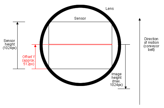
Due to aberrations at the edges of the lens, you should set an offset in the direction of Y ("Offset Y", see the following figure), generally around the half of the sensor's height (a.k.a. sensor's Y center). With Offset Y you can adjust the scan line in the direction of motion.
Scenarios
With regards to the external trigger signals provided by an incremental encoder, there are two possible scenarios:
- A conveyor belt runs continuously and so does the incremental encoder, or - like in a reverse vending machine,
- a single item is analyzed and the conveyor belt and so the incremental encoder stops after the inspection and restarts for the next item.
In the first scenario you can use the standard settings of the Balluff/MATRIX VISION devices. Please have a look at the sample Triggered line scan acquisition with exposure time of 250 us which shows how you can set the line scan mode with continuous materials and signals from the encoder. However, it is absolutely required that the external trigger is always present. During a trigger interruption, controlling or communication to the camera is not possible.
In the second scenario, the external trigger stops. If there is a heartbeat functionality in the system (e.g. with GigE Vision), there can be a halt of the system. Please have a look at the sample Triggered line scan acquisition with a specified number of image blocks and pausing trigger signals which shows how you can handle pausing trigger signals.
Sample 1: Triggered linescan acquisition with exposure time of 250 us
This sample will show you how to use the line scan mode of the sensors EV76C560 and EV76C560 - enhanced using an external trigger provided by an incremental encoder which sends a "trigger for every line" (1:1)
- Note
- You can also use the sensor EV76C570 . However, the sensor is slower due to the higher number of pixels.
In this sample, we chose an exposure time of "250 us" and to ease the calculations we used "1000 px image height".
- Note
- To get suitable image results, it might be necessary to increase the gain or the illumination.
These settings result in a max. "frame rate" of "2.5 frames per second".
To adjust the opto-mechanics (focus, distance, illumination, etc.), you can use the area mode of the sensor. That's a main advantage of an area sensor with line scan mode compared to a line scan camera!
You will need the following pins of the BVS CA-GX0 :
| Pin. | Signal (Standard version) | Description |
| 1 | GND | Common ground |
| 2 | 12V .. 24V | Power supply |
| 4 | Opto DigIn0 (line4) | The output signal A of the incremental encoder |
Setting the application in ImpactControlCenter
Summary of our sample:
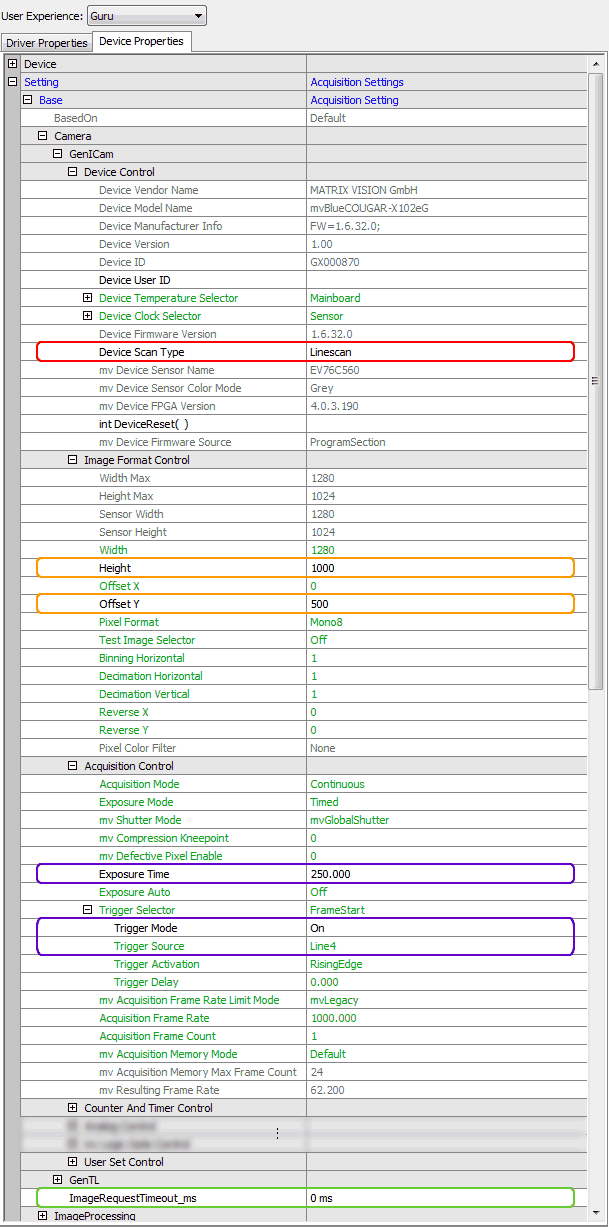
| Property name ImpactControlCenter | Setting | GenICam Control | Comment |
| Device Scan Type | "line scan" | Device Control | |
| Height (in pixels) | 1000 | Image Format Control | |
| Offset Y (in pixels) | 500 | Image Format Control | |
| Exposure Time (in microseconds) | 250.000 | Acquisition Control | |
| Trigger Mode | On | Acquisition Control | |
| Trigger Source | Line4 | Acquisition Control | |
| ImageRequestTimeout_ms (in milliseconds) | 0 ms | - | This is necessary otherwise there will be error counts and no frames are created. |
Sample 2: Triggered line scan acquisition with a specified number of image blocks and pausing trigger signals
This section will provide you with some information you have to keep in mind while working with pausing triggers and specified number of image blocks.
First of all, using BVS CA-GX0 or BVS CA-GX2 it is necessary to disable the heartbeat of the GigE Vision™ control protocol (GVCP) ("Device Link Heartbeat Mode = On") otherwise a paused trigger signal can be misinterpreted as a lost connection:

Secondly, since the conveyor belt stops sometime, the trigger will do so, too. Be sure, that the trigger signal is available until the last image block was received.
Thirdly, if you know the number of image blocks, you can use the "MultiFrame functionality" (in "Setting → Base → Camera → GenICam → Acquisition Control" set "Acquisition Mode = MultiFrame" and "Acquisition Frame Count"). This will acquire the number of image blocks and will stop the acquisition afterwards.