BVS CA-GX0-xxxxxx-xxx12x / -xxx13x / -xxx16x
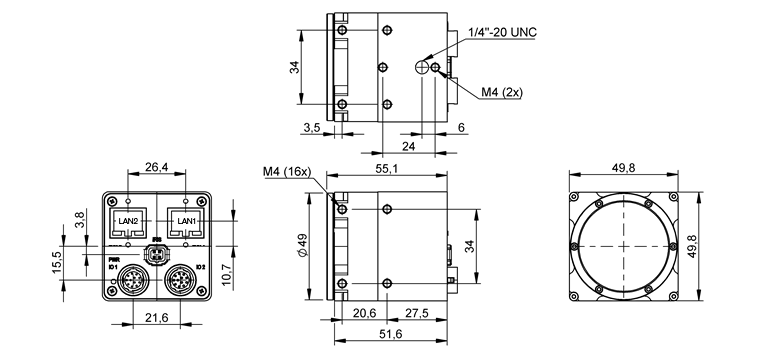
Dimensions
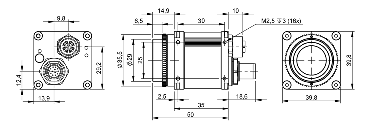
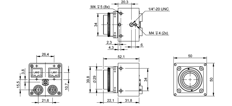
Standard model
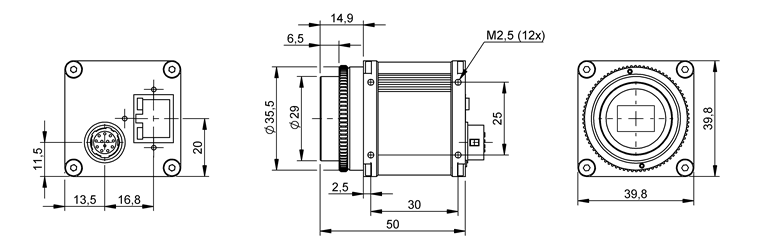
| BVS CA-GX0-xxxxxx-xxx12x / -xxx13x / -xxx16x | |
| Size of body (w x h x l) | 39.8 x 39.8 x X mm |
| C-Mount | CS-Mount | |
| X | 50 | 45 |
| Lens protrusion | C-Mount | CS-Mount |
| 8 mm (9.5 mm with max. Ø 20 mm) | 6 mm |
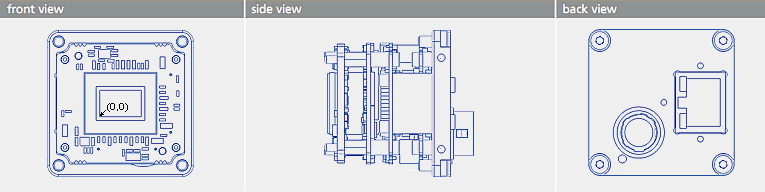
Model without housing (on demand)
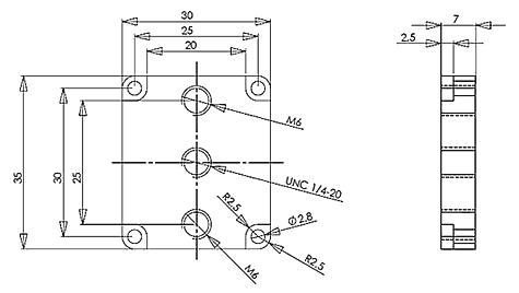
Tripod adapter
Connectors
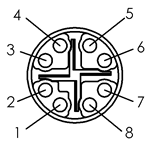
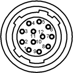
Circular connector male
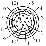
| Pin. | Signal (-xxx12x / -xxx16x) | Signal (-xxx13x option, not available for all products) | Digital I/O color code of power supply MV-DC1201 BCSX IO; Rev. 2 |
| 1 | GND (for PWR_IN) | GND (for PWR_IN)1 | gray-pink (not available with Rev. smaller than 2) |
| 2 | PWR_IN | PWR_IN1 | |
| 3 | DigOut3 (ImpactControlCenter numbering: line3) | Reserved (do not use) | white |
| 4 | Opto DigIn0 (line4) | Opto DigIn0 (line4) | brown |
| 5 | DigOut2 (line2) | N.C. | green |
| 6 | DigOut0 (line0) | Opto DigOut0 (line0) | yellow |
| 7 | Opto DigIn_GND | Opto DigIn_GND | gray |
| 8 | RS232_RX | RS232_RX | pink |
| 9 | RS232_TX | RS232_TX | blue |
| 10 | DigOut_PWR_IN (12 to 24 V supply for the outputs) | Opto DigOut_PWR_IN (12 to 24 V supply for the outputs) | red (using MV-DC1201 BCSX IO: you have to add supply for the outputs) |
| 11 | Opto DigIn1 (line5) | Opto DigIn1 (line5) | black |
| 12 | DigOut1 (line1) | Opto DigOut1 (line1) | violet |
1 Using POE and an external power supply at the same time, the external power supply will be treated prioritized.
Connector (camera side): SAMWOO SNH-10-12 (RPCB) or equivalent
Plug (matching cable plug): Hirose HR10A-10P-12S (01) or equivalent
Pinning of cable KS-BCX-HR12
| Pin. | CON 1 BVS CA-GX0 / BVS CA-GX2 | Signal | CON 2 open ended cable | Color |
| 1 | GND (for PWR_IN) | black |
| 2 | PWR_IN | brown |
| 3 | DigOut3 12 V to 24 V (ImpactControlCenter numbering: line3) | red |
| 4 | Opto DigIn0 3.3 V to 24 V (line4) | orange |
| 5 | DigOut2 (line2) | yellow |
| 6 | DigOut0 (line0) | green |
| 7 | Opto DigIn_GND | blue |
| 8 | RS232_RX | violet |
| 9 | RS232_TX | gray |
| 10 | DigOut_PWR_IN (12 to 24 V supply for the outputs) | white |
| 11 | Opto DigIn1 3.3 V to 24 V (line5) | white-black |
| 12 | Opto DigOut1 12 V to 24 V (line1) | white-brown |
| Main connector shield | main shield |
Color assignment following international code for UL wiring.
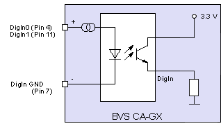
Characteristics of the digital inputs
Delay
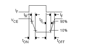
| Characteristics | Symbol | Test conditions | Typ. | Unit |
| Minimum trigger pulse width | 5 | us | ||
| Turn-On time | tON | 24 V signal | 10 | |
| Storage time | tS | 25 | ||
| Turn-Off time | tOFF | 40 |
| -xxx12x / -xxx13x / -xxx16x | |
| Notes | |
| High level | +3 to +24 V |
| Low level | 0 to +0.3 V |
| Threshold (Low --> High / High --> Low) | 2.5 V +- 0.5 V |
| Imax | 5 mA |
|
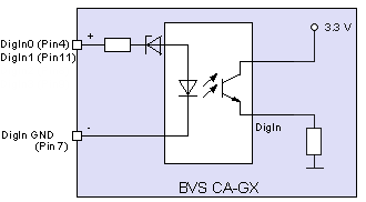
| PLC option (inputs with PLC levels only) | |
| Notes | Not available in combination with -POE option. Inputs with highest tolerance against interferences. |
| High level | +11 to +24 V |
| Low level | 0 to +8 V |
| Threshold (Low --> High / High --> Low) | 9.5 V +- 1.5 V |
| Imax | 16 mA |
|
Characteristics of the digital outputs
| BVS CA-GX0-xxxxxx-xxx12x / -xxx16x | |||||||||||||||||||||||||||
| Delay | 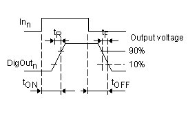
| ||||||||||||||||||||||||||
| Characteristics |
| ||||||||||||||||||||||||||
| Notes | Each output has a short circuit protection between 1 A and 1.7 A (generally 1.3 A). So if you combine two outputs with one load, the short circuit protection can have an effect. | ||||||||||||||||||||||||||

| |||||||||||||||||||||||||||
| Features | - undervoltage detection - current limitation - overtemperature protection - short circuit protection |
| BVS CA-GX0-xxxxxx-xxx13x (POE) | ||||||||||||||||||||||||||||||||||||||||||||||||||||
| Delay |
| |||||||||||||||||||||||||||||||||||||||||||||||||||
| Characteristics |
| |||||||||||||||||||||||||||||||||||||||||||||||||||
| Notes | ||||||||||||||||||||||||||||||||||||||||||||||||||||
| ||||||||||||||||||||||||||||||||||||||||||||||||||||
| Features |
Measurement conditions : VCC = 24 V; -25 °C < TJ < 125 °C, RL = 48 Ohm
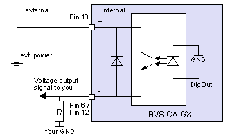
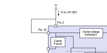
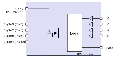
Example circuit 1: High-side switch uses power supply of the camera
In this case you have to bridge pin 2 (external power supply) with pin 10 (the supply of the outputs):
Example circuit 2: High-side switch uses separate power supply
Following figure shows, how to connect, for example, high power flash LEDs in series at the direct drive output at pin 3:
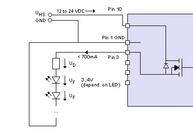
A 24V power supply is connected at pin 10. To protect the LEDs a series resistor is needed, which can be calculated in this way:
Voltage:
U_HS - (n * U_F) = U_D
Series resistor:
      U_D
R = --------
     0.7A
Power:
P = duty cycle * U_D * I
The duty cycle is a coefficient < 1, which defines the power of the resistor. It is the ratio of the time period while current flows compared to the total time. If the current always flows, "P = U * I" will be the determining factor. If the current only flows a hundredth of time (duty cycle 1%), a resistor with a hundredth of power will be enough.
- Note
- For the connected LEDs and the ground of the external power supply, you have to use the ground of the camera at Pin 1.
- Attention
- "Surge"
The series resistor has to handle the power, which depends on the duty cycle and the frequency. Otherwise surge is the result and can damage the used LEDs.
→ Calculate the suitable size of the series resistor using the above mentioned formulas.
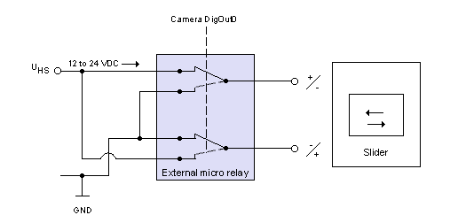
Example circuit 3: Control motorized lens with BVS CA-GX0
It is possible to control a motorized lens using the BVS CA-GX0. However, an external micro relay is necessary which changes the polarity of the lens slider when triggered by the camera's digital output. The following figure shows an example circuit:
RJ45 100/1000 MBit Ethernet
With the -POE option, the camera is a class 2 compliant PoE device.
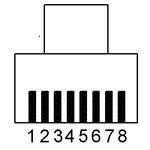
| Pin. | Signal | I/O | Comment |
| 1 | BI_DA+ | bi | data positive |
| 2 | BI_DA- | bi | data negative |
| 3 | BI_DB+ | bi | data positive |
| 4 | BI_DC+ | bi | data positive |
| 5 | BI_DC- | bi | data negative |
| 6 | BI_DB- | bi | data negative |
| 7 | BI_DD+ | bi | data positive |
| 8 | BI_DD- | bi | data negative |
- Note
- The Ethernet signals are galvanically isolated from the camera electronics and camera housing.
RJ45 LED states
| States | LED1 | LED2 |
| 1Gb transmission | Green light on | Yellow blink on |
| 100Mb transmission | Green light off1 | Yellow blink on |
1 Hardware Rev 5.xx - Green light on.
Signal LED
The BVS CA-GX0 features a RGB LED. There are following states:
Typical start sequence (LLA)
- See also
- LLA
| State | LED color |
| FPGA loaded | White on |
| Self-test running | Green on |
| Waiting for Ethernet connection | White blink |
| LLA (auto IP) | Green blink |
| LLA got | Green on |
| Waiting for client | Blue on |
Typical start sequence (DHCP)
- See also
- DHCP
| State | LED color |
| FPGA loaded | White on |
| Self-test running | Green on |
| Waiting for Ethernet connection | White blink |
| DHCP request | Blue blink |
| DHCP got | Bright Blue |
| Waiting for client | Blue on |
Typical start sequence (Fixed IP)
- See also
- Fixed IP
| State | LED color |
| FPGA loaded | White on |
| Self-test running | Green on |
| Waiting for Ethernet connection | White blink |
| Fixed IP | Bright Green |
| Waiting for client | Blue on |
General behavior
| State | LED color |
| Starting ImpactControlCenter | |
| Connected, streaming off | Yellow on |
| Streaming on | Green on |
| Error | |
| Red on | |
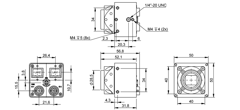
BVS CA-GX0-xxxxxx-xxx14x (POE-I) / -xxxC4x (POE-IP67C)
Dimensions
Power over Ethernet model (POE-I)
Compact IP67 version (POE-IP67C)
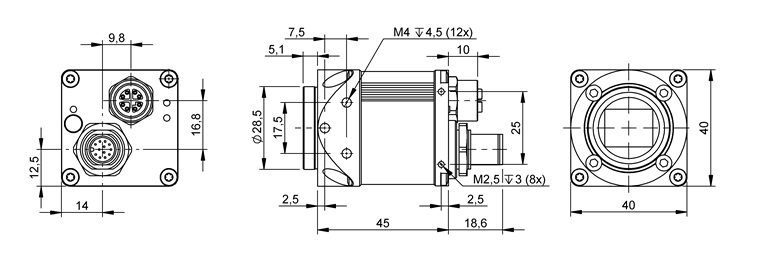
Connectors
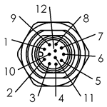
Circular connector male (POE-I Rev. 2.00)
- Note
- The power pinning is different to the circular connector male pinning due to the different cable color scheme.
| Pin. | Signal | Description |
| 1 | PWR_IN 1 | |
| 2 | GND (for PWR_IN) 1 | |
| 3 | DigOut3 | ImpactControlCenter numbering: line3, high side solid state relays |
| 4 | Opto DigIn0 | line4, opto-coupler |
| 5 | DigOut2 | line2, high side solid state relays |
| 6 | DigOut0 | line0, high side solid state relays |
| 7 | Opto DigIn_GND | Ground for opto-coupler (In) |
| 8 | Opto DigIn2 | line6, opto-coupler |
| 9 | Opto DigIn3 | line7, opto-coupler |
| 10 | DigOut_PWR_IN | 10 to 28 V supply for the high side outputs, ground via pin 2 "PWR_IN-/GND" |
| 11 | Opto DigIn1 | line5, opto-coupler |
| 12 | DigOut1 | line1, high side solid state relays |
1 Using POE and an external power supply at the same time, the external power supply will be treated prioritized.
Camera connector (male): Binder M12/12pol 09-3491-90-12 or equivalent
Matching cable and connector (female):
- Binder 79-3490-32-12 | M 12 | A-coded series 763, length 2m open end
- Binder 79-3490-35-12 | M 12 | A-coded series 763, length 5m open end
- Note
- - All inputs (DigIn1..DigIn4 and GND Opto-coupler) are galvanically isolated from the camera electronics.
- The digital inputs have the same characteristics as the inputs of mvBlueCOUGAR-X with PLC option.
- The digital outputs have the same characteristics as the outputs of the standard mvBlueCOUGAR-X.
Characteristics of the digital inputs
Delay
| Characteristics | Symbol | Test conditions | Typ. | Unit |
| Minimum trigger pulse width | 5 | us | ||
| Turn-On time | tON | 24 V signal | 10 | |
| Storage time | tS | 44 | ||
| Turn-Off time | tOFF | 95 |
| Notes | Inputs with highest tolerance against interferences. |
| High level | +11 to +24 V |
| Low level | 0 to +8 V |
| Threshold (Low --> High / High --> Low) | 9.5 V +- 1.5 V |
| Imax | 16 mA |
|
|
Characteristics of the digital outputs
| Delay |
| ||||||||||||||||||||||||||
| Characteristics |
| ||||||||||||||||||||||||||
| Notes | Each output has a short circuit protection between 1 A and 1.7 A (generally 1.3 A). So if you combine two outputs with one load, the short circuit protection can have an effect. | ||||||||||||||||||||||||||
| |||||||||||||||||||||||||||
| Features | - undervoltage detection - current limitation - overtemperature protection - short circuit protection |
Measurement conditions : VCC = 24 V; -25 °C < TJ < 125 °C, RL = 48 Ohm
M12 X-coded 100/1000 MBit Ethernet (option POE-I Rev. 2.00)
| Pin. | Signal |
| 1 | BI_DA+ |
| 2 | BI_DA- |
| 3 | BI_DB+ |
| 4 | BI_DB- |
| 5 | BI_DD+ |
| 6 | BI_DD- |
| 7 | BI_DC- |
| 8 | BI_DC+ |
- Note
- The Ethernet signals are galvanically isolated from the camera electronics.
BVS CA-GX2
Dimensions
Standard model with lens holder type 1 (-x2xxxx)
| BVS CA-GX2 | |
| Size of body (w x h x l) | 50 x 50 x 56.8 mm |
Standard model with lens holder type 2 (-x1xxxx / -x5xxxx)
| BVS CA-GX2 | |
| Size of body (w x h x l) | 50 x 50 x 56.8 mm |
Hi-res model with M42 mount (-xNxxxx)
| BVS CA-GX2-0315Z | |
| Size of body (w x h x l) | 50 x 50 x 55.5 mm |
Available M42 adapter:
| Part code | Description |
| BAM AD-VS-020-M42/FM-1 | Adapter from M42 at F-mount |
| BAM AD-VS-020-M42/M35X0,75-1 | Adapter from M42 to M35 distance 5.5mm for TFL lenses |
Connectors
Circular connector male
| Pin. | Signal | Digital I/O color code of power supply MV-DC1201 BCSX IO; Rev. smaller than 2 | Digital I/O color code of power supply MV-DC1201 BCSX IO; Rev. 2 |
| 1 | GND (for PWR_IN) | GND | x |
| 2 | PWR_IN | ||
| 3 | DigOut3 (ImpactControlCenter numbering: line3) | white | white |
| 4 | Opto DigIn0 (line4) | brown | brown |
| 5 | DigOut2 (line2) | green | green |
| 6 | DigOut0 (line0) | yellow | yellow |
| 7 | Opto DigIn_GND | gray | gray |
| 8 | RS232_RX | pink | pink |
| 9 | RS232_TX | blue | blue |
| 10 | DigOut_PWR_IN (12 to 24 V supply for the outputs) | red | red |
| 11 | Opto DigIn1 (line5) | black | black |
| 12 | DigOut1 (line1) | violet | violet |
Connector (camera side): SAMWOO SNH-10-12 (RPCB) or equivalent
Plug (matching cable plug): Hirose HR10A-10P-12S (01) or equivalent
We recommend to use the connection cable KS-BCX-HR12 .
Circular connector female
| Pin. | Signal | Description | Color of open end of cable KS-BCXD-HR12 |
| 1 | Opto DigIn2 (line6) | Additional input with the same characteristics as the inputs of the male connector | blue |
| 2 | Opto DigIn_GND | Ground of DigIn2 and DigIn3 | red |
| 3 | Opto DigIn3 (line7) | Additional inputs with the same characteristics as the inputs of the male connector | pink |
| 4 | Focus+ | Focus control for motorized lenses (12V PWM) | gray |
| 5 | Focus- | yellow | |
| 6 | Zoom+ | Zoom control for motorized lenses | green |
| 7 | Zoom- | brown | |
| 8 | Iris+ | Lens aperture control for lenses with three motors | white |
| 9 | Iris- | black | |
| 10 | Channel4+ | Optional fourth channel | light blue |
| 11 | Channel4- | orange | |
| 12 | GND | Ground | violet |
Connector (camera side): SAMWOO SN-10-12 (RPCB) or equivalent
Plug (matching cable plug): Hirose HR10A-10P-12P (01) or equivalent
Characteristics of the digital inputs
Delay
| Characteristics | Symbol | Test conditions | Typ. | Unit |
| Minimum trigger pulse width | 5 | us | ||
| Turn-On time | tON | 24 V signal | 10 | |
| Storage time | tS | 25 | ||
| Turn-Off time | tOFF | 40 |
| Standard | |
| Notes | |
| High level | +3 to +24 V |
| Low level | 0 to +0.3 V |
| Threshold (Low --> High / High --> Low) | 2.5 V +- 0.5 V |
| Imax | 5 mA |
|
|
Characteristics of the digital outputs
| Delay |
| ||||||||||||||||||||||||||
| Characteristics |
| ||||||||||||||||||||||||||
| Notes | Each output has a short circuit protection between 1 A and 1.7 A (generally 1.3 A). So if you combine two outputs with one load, the short circuit protection can have an effect. | ||||||||||||||||||||||||||
|
| |||||||||||||||||||||||||||
| Features | - undervoltage detection - current limitation - overtemperature protection - short circuit protection |
Measurement conditions : VCC = 24 V; -25 °C < TJ < 125 °C, RL = 48 Ohm
Example circuit 1: High-side switch uses power supply of the camera
In this case you have to bridge pin 2 (external power supply) with pin 10 (the supply of the outputs):
Example circuit 2: High-side switch uses external (higher) power supply
Following figure shows, how to connect, for example, high power flash LEDs in series at the direct drive output at Pin 3:
A 24V power supply is connected at Pin 10. To protect the LEDs a series resistor is needed, which can be calculated in this way:
Voltage:
U_HS - (n * U_F) = U_D
Series resistor:
      U_D
R = --------
     0.7A
Power:
P = dutycycle * U_D * I
The duty cycle is a coefficient < 1, which defines the power of the resistor. It is the ratio of the time period while current flows compared to the total time. If the current always flows, "P = U * I" will be the determining factor. If the current only flows a hundredth of time (duty cycle 1%), a resistor with a hundredth of power will be enough.
- Note
- For the connected LEDs and the ground of the external power supply, you have to use the ground of the camera at Pin 1.
- Attention
- The series resistor has to handle the power, which depends on the duty cycle and the frequency.
RJ45 100/1000 MBit Ethernet
| Pin. | Signal | I/O | Comment |
| 1 | BI_DA+ | bi | data positive |
| 2 | BI_DA- | bi | data negative |
| 3 | BI_DB+ | bi | data positive |
| 4 | BI_DC+ | bi | data positive |
| 5 | BI_DC- | bi | data negative |
| 6 | BI_DB- | bi | data negative |
| 7 | BI_DD+ | bi | data positive |
| 8 | BI_DD- | bi | data negative |
- Note
- The Ethernet signals are galvanically isolated from the camera electronics and camera housing.
RJ45 LED states
| States | LED1 | LED2 |
| 1Gb transmission | Green light on | Yellow blink on |
| 100Mb transmission | Green light off1 | Yellow blink on |
1 Hardware Rev 5.xx - Green light on.
Video iris
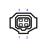
This pin configuration is compliant to the JEITA standard:
| Pin | Signal |
| 1 | IRIS_PWR_IN (12 V) |
| 2 | NC |
| 3 | IRIS_CTRL |
| 4 | Ground |
- Attention
- "Wrong polarity"
Please check the wiring of your video iris lenses, because there are brands which uses the standard 4-pin connector with non-standard wiring. Otherwise you can damage the lens.
Signal LED
The BVS CA-GX2 features a RGB LED. There are following states:
Typical start sequence (LLA)
- See also
- LLA
| State | LED color |
| FPGA loaded | White on |
| Self-test running | Green on |
| Waiting for Ethernet connection | White blink |
| Waiting for LLA (auto IP) | Green blink |
| Waiting for client | Blue on |
Typical start sequence (DHCP)
- See also
- DHCP
| State | LED color |
| FPGA loaded | White on |
| Self-test running | Green on |
| Waiting for Ethernet connection | White blink |
| Waiting for DHCP | Light blue blink |
| Waiting for client | Blue on |
Typical start sequence (Fixed IP)
- See also
- Fixed IP
| State | LED color |
| FPGA loaded | White on |
| Self-test running | Green on |
| Waiting for Ethernet connection | White blink |
| Waiting for client | Blue on |
General behavior
| State | LED color |
| Starting ImpactControlCenter | |
| Connected, streaming off | Yellow on |
| Streaming on | Green on |
| Error | |
| Red on | |
Summary of components
| Features | BVS CA-GX0 G/C | BVS CA-GX2 G/C | |||||
| Standard version | "-PLC" option (inputs with PLC levels only) | Power over Ethernet | Power over Ethernet Industrial | ||||
| IP40 | IP67 | ||||||
| Image Memory | 64 MByte (128 MB option available: BVS CA-GX1) | 256 MByte | |||||
| Proc. Memory | 64 MByte | ||||||
| ADC resolution | CMOS: ADC on chip | ||||||
| Inputs | 2 | 2 (PLC levels only) | 2 | 4 | 4 | ||
| Type | opto-isolated with current limiters | ||||||
| Outputs | 4 | 2 | 4 | 4 | |||
| Type | high-side solid state relay | opto-isolated | high-side solid state relay | high-side solid state relay | |||
| Ethernet | 100/1000 Mbit | RJ45 | M12 X-coded | 2x RJ45 | |||
| Optics | |||||||
| Lens Mount (Focal Distance) | C-mount (17.526 mm in air), CS-mount (12.5 mm in air), optional S-mount | ||||||
| Lens Protrusion | 6 .. 8 mm | ||||||
| Environment | |||||||
| Ambient Temperature | |||||||
| Operation | 0..45 deg C / 30 to 80% RH | 0..45 deg C / 0 to 100% RH | 0..45 deg C / 30 to 80% RH | ||||
| Storage | -20..60 deg C / 20 to 90% RH | -20..60 deg C / 0 to 100% RH | -20..60 deg C / 20 to 90% RH | ||||
| Protection class 1 | IP40 | IP67 | IP30 | ||||
| Additional features | temperature sensor | temperature sensor video iris lens control (zoom, focus, iris) | |||||
| Weight without lens | approx. 110 g | approx. 127 g | approx. 170 g, mvBlueCOUGAR-XD1031: approx. 215 g | ||||
| Power supply (PWR_IN) | |||||||
| DC | 10 to 28 V | ||||||
| Pmax | 6.5 W | 9 W | |||||
| Peak current draw | 1.0 A | ||||||
| Reverse polarity protection | up to 28 V | ||||||
1 not evaluated by UL
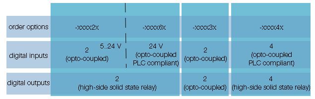
Summary of available digital I/O's
Summary of advanced features
The following table shows an excerpt of the advanced features.
For the complete list, please use the "Product Comparison" in Appendix B. Product Comparison .
| Advanced features | BVS CA-GX0 G/C | BVS CA-GX2 G/C | |
| MultiFrame, etc. | √ | √ | |
| Trigger Overlap | √ | √ | |
| Temperature | upper limit (<= 255 deg C) lower limit (>= 0 deg C) | √ | √ |
| User Sets | 5 config sets storable | √ | √ |
| User Data | 512 byte of EEPROM data | √ | √ |
| FPGA LUT | on the fly on the camera | √ | √ |
| Timestamp | microsecond precise camera individual 64 bit counter | √ | √ |
| FFC | full AOI, 14 bit to 14 bit (12 bit coeff.), pixel to pixel | √ | x |
| Counter / timer | timers can be used for pulse width modulation | 4 counters, 2 timers | 8 counters, 2 timers |
| AEC | √ | √ | |
| AGC | √ | √ | |
| White balance | √ | √ | |
| Auto white balance | √ | √ | |
| RGB-to-YUV conversion | √ | √ | |
| CCM | √ | √ | |
| Timestamp for inter-camera synchronization | √ | √ | |
| Pretrigger | √ | √ | |
| Linescan mode | -102e -102eGE -104e | √ | √ |
| Logic gates | √ | √ | |
| Chunk Data | √ | √ | |
| Multicast | √ | √ | |
| Application switchover | √ | √ | |
| Frame average | x | x | |