Installation
Warning
The instructions on Safety related to the 3D stereo camera must be read and understood prior to installation.
Mounting
The 3D stereo camera is intended to be mounted on a wall or ceiling above the target area. It is not intended to be used in dynamic applications mounted to a robot wrist. It is the customer’s responsibility to provide an adequate mounting bracket.
For mounting, the 3D stereo camera provides an M4 and M5 thread pattern on its top and bottom sides (see Fig. 7). A medium-strength thread-locker or Tuflok® screws must be used to protect against vibrations. M5 screws must be tightened to 4.0 Nm, M4 screws must be tightened to 3.3 Nm.
Warning
The 3D stereo camera cannot be mounted on the end-effector of a robot.
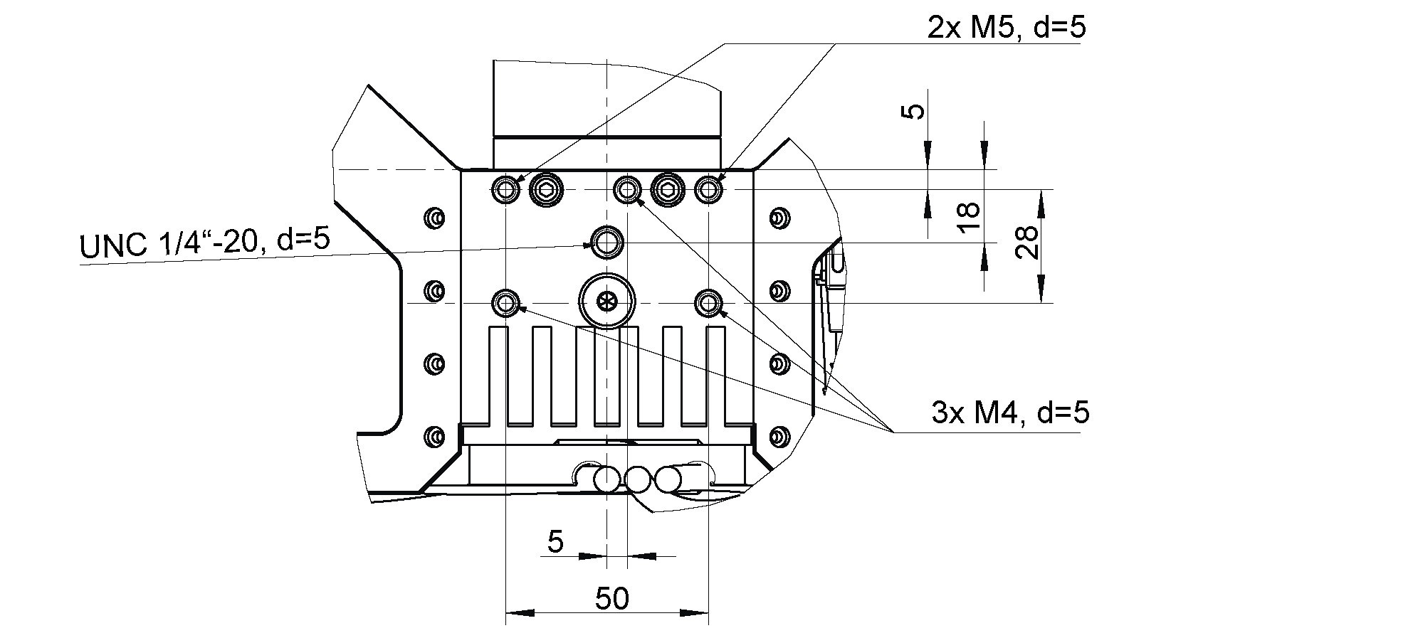
Fig. 7 Mounting of the 3D stereo camera
Only the surface containing the thread pattern must be in contact with the mounting bracket, all other surfaces must remain free. At least 10 cm clearance must be provided behind the 3D stereo camera to facilitate adequate air flow for cooling.
Power-up
Note
Always fully connect and tighten all M12 connectors on the 3D stereo camera before turning on the power supply.
After connecting the system to power, the LED on the front of the 3D stereo camera should immediately illuminate.
Warning
Do not look into the projector lens in the center of the 3D stereo camera or into the light beam at any point during startup or operation.
Connecting
Connecting to the SGM®Producer
For using the 3D stereo camera as high-resolution RGBD camera, Balluff offers the SGM®Producer, which is a GenICam compatible transport layer.
Via the mvIMPACT Acquire API, the producer can be used with different programming languages, with Halcon, as well as with any other GenICam compatible application. It can be downloaded free of charge from https://www.balluff.com and installed on Windows and Ubuntu computers with an Nvidia graphics card.
It is strongly recommended to connect both network cables directly to 1 gigabit Ethernet ports of the computer. A network switch can only work if the network link between the switch and the computer has a bandwidth of more than 2 gigabit, e.g. 2.5, 5 or 10 gigabit.
In the default network configuration and according to the GigE Vision® standard, the 3D stereo camera cameras will try to obtain their configuration from a DHCP server and fall back to the Link-Local self-configuration protocol, if no DHCP server can be found. For direct connection without a DHCP server, the Ethernet ports of the computer should be configured for Link-Local network. It is also possible to manually configure IP addresses of the left and right camera.
The tool mvIPConfigure can be used for changing the network settings and the IP address. It is contained in the mvIMPACT Acquire driver for gigabit Ethernet cameras. The driver can be downloaded from https://www.balluff.com. Alternatively, any other GigE Vision 2.0 compatible configuration tool can be used.
For adjusting the focus, checking and calibrating the 3D stereo camera, as explained in the next sections, the SGM®Producer package contains a calibration program, called rc_calib.
Adjust focus
It is highly recommended to check and adjust the focus of the 3D stereo camera for the actual working range. Please note that the depth of focus range is limited due to the high resolution of the camera and must be adapted to the working range of the application. At close distance, the depth of focus range is much smaller than at higher distance. Therefore, the minimum distance for focusing should be chosen as far away as useful for the application. Please contact support in case of questions regarding working distance and calibration of the 3D stereo camera.
For users of the SGM®Producer, the focus helper can be found in the rc_calib calibration program after selecting the 3D stereo camera with , and specifying the grid size.
The bars on the right side of the image report the blur of the calibration grid, thus a minimum is desirable. The grid should be placed in the minimum and maximum working distance for checking the current blur. A value near the lowest dividing line is quite optimal.
If focus adjustment is needed, the lens caps of the left and right cameras must be removed as shown in Fig. 8.
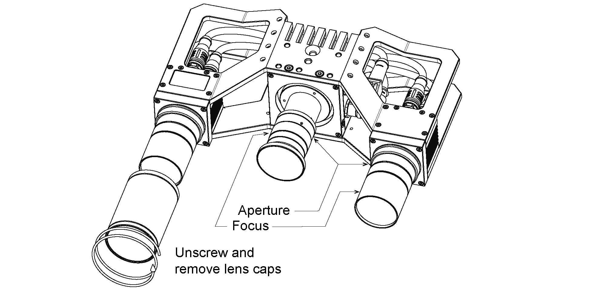
Fig. 8 Removing of lens caps for re-focussing and changing aperture
The focus ring and the aperture ring are locked by 3 screws for each ring as shown in Fig. 9. All three screws must be loosened for moving the ring.
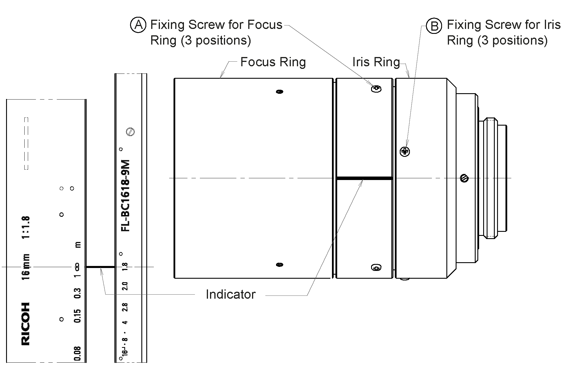
Fig. 9 Location of screws for focus and aperture ring
For setting the focus correctly, the calibration grid should be placed in the middle of the working range. Then, the focus ring should be turned until the bars in the images become a minimum. After focusing in this way, the grid should be placed at the minimum and maximum working distance. If the blur is unsatisfactory at the minimum and maximum working distance (e.g. near the second dividing line or higher), the aperture can be closed a bit, i.e. choosing a higher aperture number. Please be aware that this increases exposure time and potentially gain, which increases noise in the image. The optimal tradeoff is application dependent.
Warning
The same aperture setting must be used for the left and right camera to avoid degraded image processing performance. Please validate that the left and right images appear with the same brightness.
After adjusting focus and aperture, all screws must be tightened and the lens caps re-attached.
To change focus and aperture settings of the projector, loosen the three small fixing Phillips screws on the respective ring of the projector lens, turn the ring to the desired setting and lightly tighten the screws again. For focus adjustments, the projector should be turned on permanently by setting the Out1 mode to High in the category DigitalIOControl. For aperture adjustments, Out1 should be set to ExposureAlternateActive and exposure mode should be set to ‚Auto‘ in the category AcquisitionControl. Perfectly focusing the projector is not crucial. Slightly blurred projection will not degrade the depth image.
Calibration
After checking and potentially adjusting the focus, the next step is to check calibration. This step should never be skipped and is mandatory. Please note that the working range of the 3D stereo camera is pre-defined and the calibration should be checked for the minimum and maximum working range. Please contact support in case of questions regarding working distance and calibration of the 3D stereo camera.
The manual of the smart 3D camera explains checking and re-calibrating in detail. The procedure that is described their can be applied in the same way to the SGM®Producer, by using the rc_calib program that is provided with the producer.
Warning
It is mandatory to always check calibration after mounting the 3D stereo camera, changing the focus or aperture. After calibration, also a new hand-eye calibration is required.