Hardware specification
Note
The following hardware specifications are provided here as a general reference; differences with the product may exist.
Scope of delivery
Standard delivery for the 3D stereo camera includes
- 3D stereo camera,
- Quickstart guide.
The following accessories are required additionally
- Calibration grid large (A3),
- 2 x 10 m gigabit Ethernet network cables,
- 10 m power cable with M12 connector and one open end.
The full manual is online available in digital form at https://www.balluff.com.
Note
The following items are not included in the delivery unless otherwise specified:
- Couplings, adapters, mounts,
- Power supply unit and fuses.
Please refer to Accessories for suggested cables.
The following picture shows the important parts of the 3D stereo camera which are referenced later in the documentation.
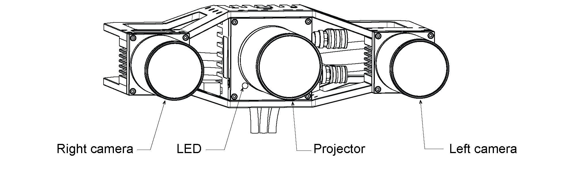
Fig. 2 Parts description
Technical specification
The technical specification of the 3D stereo camera is shown in Table 1. The given depth image frame rate can be reached with the SGM®producer on a computer with an Nvidia RTX2070 GPU. Higher frame rates (up to 9 Hz) are possible with faster graphics cards.
| 3D stereo camera | |
|---|---|
| Image resolution | 4112 x 3008 pixels monochrome |
| Framerate | 9 Hz |
| Focal length | 16 mm |
| Field of view | Horizontal: 47.5°, Vertical: 35.7° |
| Workspace | 670 mm x 640 mm @ 1.0 m distance
1550 mm x 1280 mm @ 2.0 m distance
2430 mm x 1920 mm @ 3.0 m distance
3310 mm x 2560 mm @ 4.0 m distance
|
| Depth image | 4112 x 3008 pixel (Full) @ 2.8 Hz (Nvidia RTX2070)
2056 x 1504 pixel (High) @ 4.6 Hz (Nvidia RTX2070)
1028 x 752 pixel (Medium) @ 9 Hz (Nvidia RTX2070)
686 x 502 pixel (Low) @ 9 Hz (Nvidia RTX2070)
|
| Cooling | Passive |
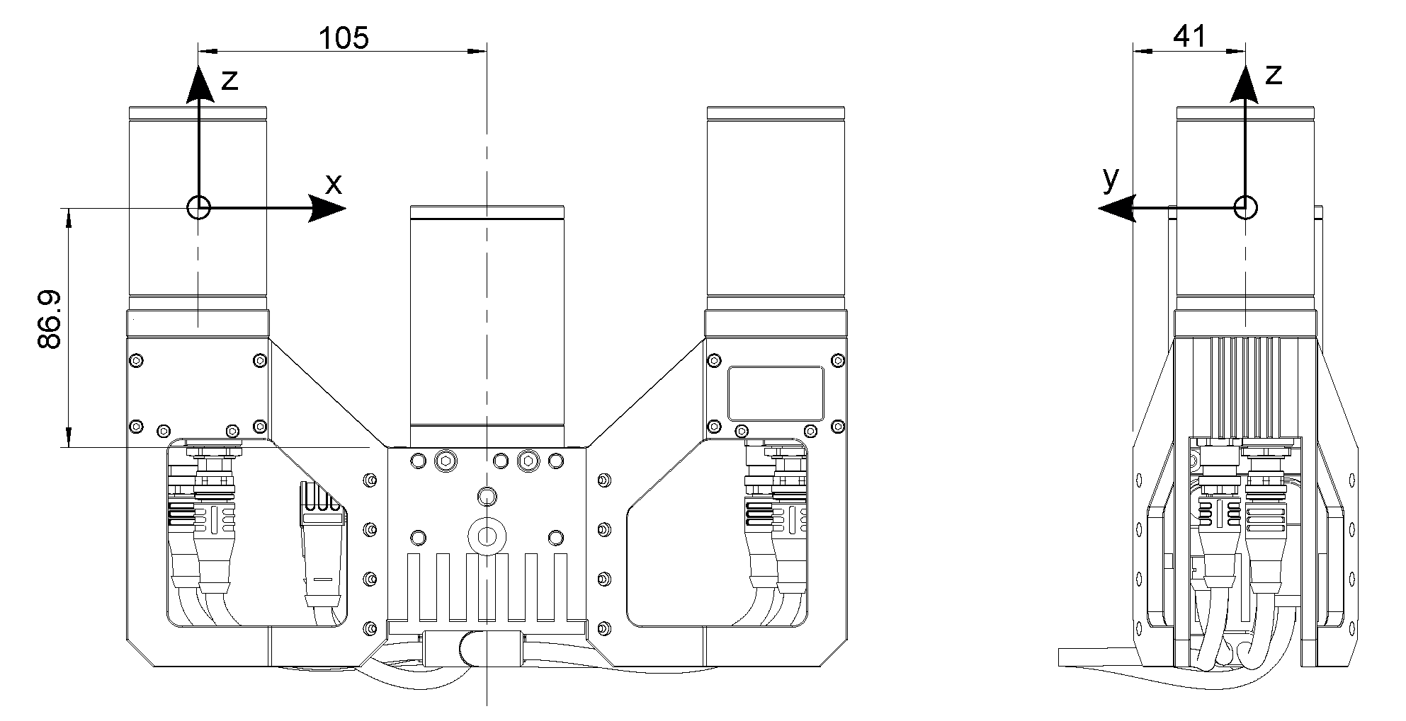
| Baseline | 210 mm |
| Size (W x H x L) | 262 mm x 204 mm x 82 mm |
| Mass | 1.64 kg |
The depth image range of the 3D stereo camera depends on the depth image quality, the specified maximum depth range and the available GPU memory. Depth ranges at closer distance are much smaller than depth ranges at far distances. Table 2 shows examples of resulting depth ranges with 3.4 Gbytes of GPU memory. Larger depth ranges are possible by using the SGM®producer with a graphics card that offers more GPU memory.
| 3D stereo camera | |
|---|---|
| Full depth quality | 0.89 m to 1.00 m
1.60 m to 2.00 m
2.18 m to 3.00 m
2.65 m to 4.00 m
|
| High depth quality | 0.52 m to 1.00 m
0.66 m to 2.00 m
0.75 m to 3.00 m
0.80 m to 4.00 m
1.00 m to infinity
|
| Medium and low depth quality | 0.52 m to infinity |
The resolution and accuracy at different distances is given in Table 3 for the recommended high depth quality. In full depth quality, the resolution and accuracy will be better by a factor of 2. Similarly, in medium quality, the resolution and accuracy will be about 2 times worse than shown in the table.
| distance | 3D stereo camera | |
|---|---|---|
| Lateral resolution | 1.0 m
2.0 m
3.0 m
4.0 m
|
0.4 mm
0.9 mm
1.3 mm
1.7 mm
|
| Depth resolution | 1.0 m
2.0 m
3.0 m
4.0 m
|
0.1 mm
0.5 mm
1.2 mm
2.0 mm
|
| Average depth accuracy | 1.0 m
2.0 m
3.0 m
4.0 m
|
0.5 mm
2.0 mm
4.6 mm
8.2 mm
|
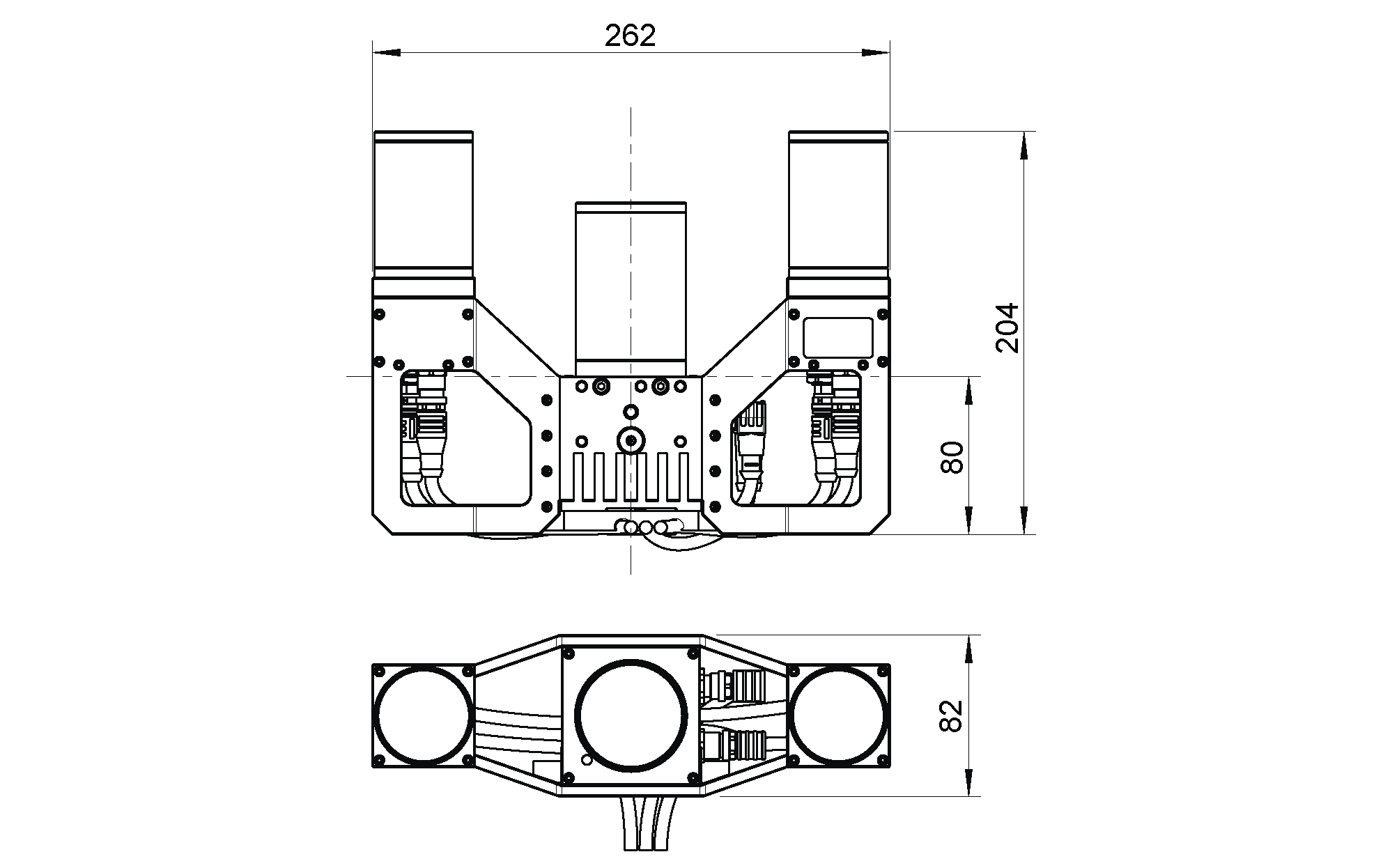
Fig. 3 Overall dimensions of the 3D stereo camera in millimeters
CAD models of the 3D stereo camera can be downloaded from https://www.balluff.com on the corresponding product page. The CAD models are provided as-is, with no guarantee of correctness.
Environmental and operating conditions
The 3D stereo camera is designed for industrial applications. Always respect the storage, transport, and operating environmental conditions outlined in Table 4.
| 3D stereo camera | |
|---|---|
| Storage/Transport temperature | -20 °C to 60 °C |
| Operating temperature | 0 °C to 45 °C (passive cooling) |
| Relative humidity (non condensing) | 20 % to 80 % |
| Protection class | IP54 |
| Others |
|
The 3D stereo camera is designed for an operating temperature (surrounding environment) of 0 °C to 45 °C and relies on convective (passive) cooling. Unobstructed airflow, especially around the cooling fins, needs to be ensured during use. The 3D stereo camera should only be mounted using the provided mechanical mounting interface, and all parts of the housing must remain uncovered. A free space of at least 10 cm extending in all directions from the housing, and sufficient air exchange with the environment is required to ensure adequate cooling. Cooling fins must be free of dirt and other contamination.
Power-supply specifications
The 3D stereo camera needs to be supplied by a DC voltage source. The camera’s standard package does not include a DC power supply. Each 3D stereo camera must be connected to a separate power supply. Connection to domestic grid power is only allowed through a power supply certified as EN55011 Class B.
| Min | Nominal | Max | |
|---|---|---|---|
| Supply voltage | 22.0 V | 24 V | 26.0 V |
| Max power consumption | 48 W | ||
| Overcurrent protection | Supply must be fuse-protected to a maximum of 2 A | ||
| EMC compliance | see Electronical and safety standards | ||
Warning
Exceeding maximum power rating values may lead to damage of the 3D stereo camera, power supply, and connected equipment.
Warning
A separate power supply must power each 3D stereo camera.
Warning
Connection to domestic grid power is allowed through a power supply certified as EN55011 Class B only.
Wiring
The 3D stereo camera is delivered with a sync cable already connected between projector and cameras. It is the customer’s responsibility to connect the two provided M12 X-coded network cables to the left and right camera, as well as the power cable with an angled M12 connector to the projector (see Fig. 4). The network cables must be clipped into the cable guide for strain relief. All cables must be secured to the mounting bracket.
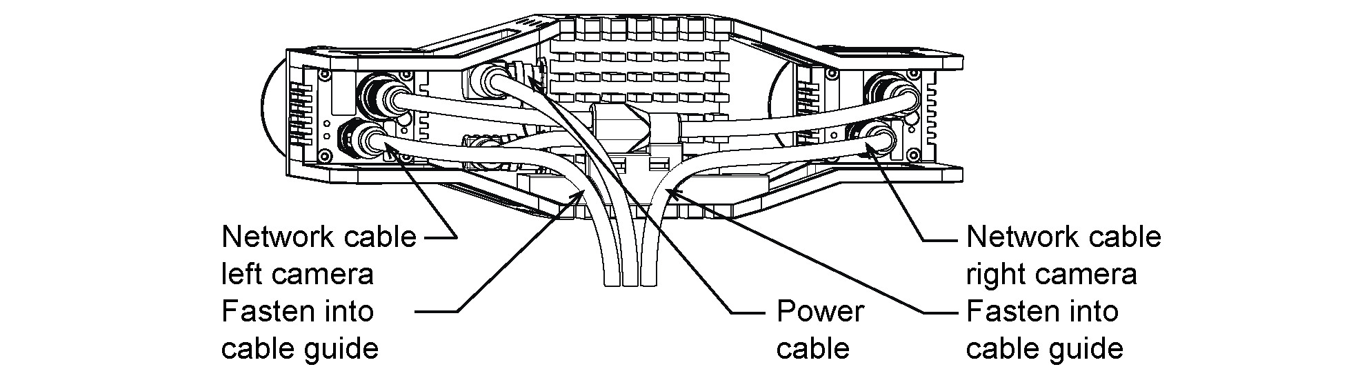
Fig. 4 Locations of the electrical connections for the 3D stereo camera
Warning
Due to the voltage drop, the maximum power cable length is limited to 15 m. The supply voltage should be set to the specified 24 V and must not be set above 26 V due to the highly variable current draw of the 3D stereo camera.
Warning
Proper cable management is mandatory. Cabling must always be secured to the 3D stereo camera
mount with a strain-relief clamp so that no forces due to cable movements are exerted on the 3D stereo camera’s
M12 connectors. Enough slack needs to be provided to allow for full range of movement of the camera
without straining the cable. The cable’s minimum bend radius (i.e.  ) needs to be observed.
Pin assignments for the power connector are given in Table 6.
| Pin | Cable Color | Designation | Details |
|---|---|---|---|
| 1 | White | nc | |
| 2 | Brown | Power +24 V | 2 A @ 24 V |
| 3 | Green | GPIO In 1 | 12-24 V, 15 mA max. |
| 4 | Yellow | GPIO GND | |
| 5 | Grey | GPIO Vcc | 5-24 V, 50 mA max. |
| 6 | Pink | GPIO Out 1 | Projector exposure signal |
| 7 | Blue | Power GND | |
| 8 | Red | GPIO Out 2 |
Note
Please note that in hardware revisions prior to 1.1 the pins number 3 and 4 were not connected.
GPIOs are decoupled by photocouplers. GPIO Out 1 by default provides an exposure sync signal with a logic high level for the duration of the image exposure. Pins of unused GPIOs should be left floating. GPIO circuitry and specifications are shown in Fig. 5.
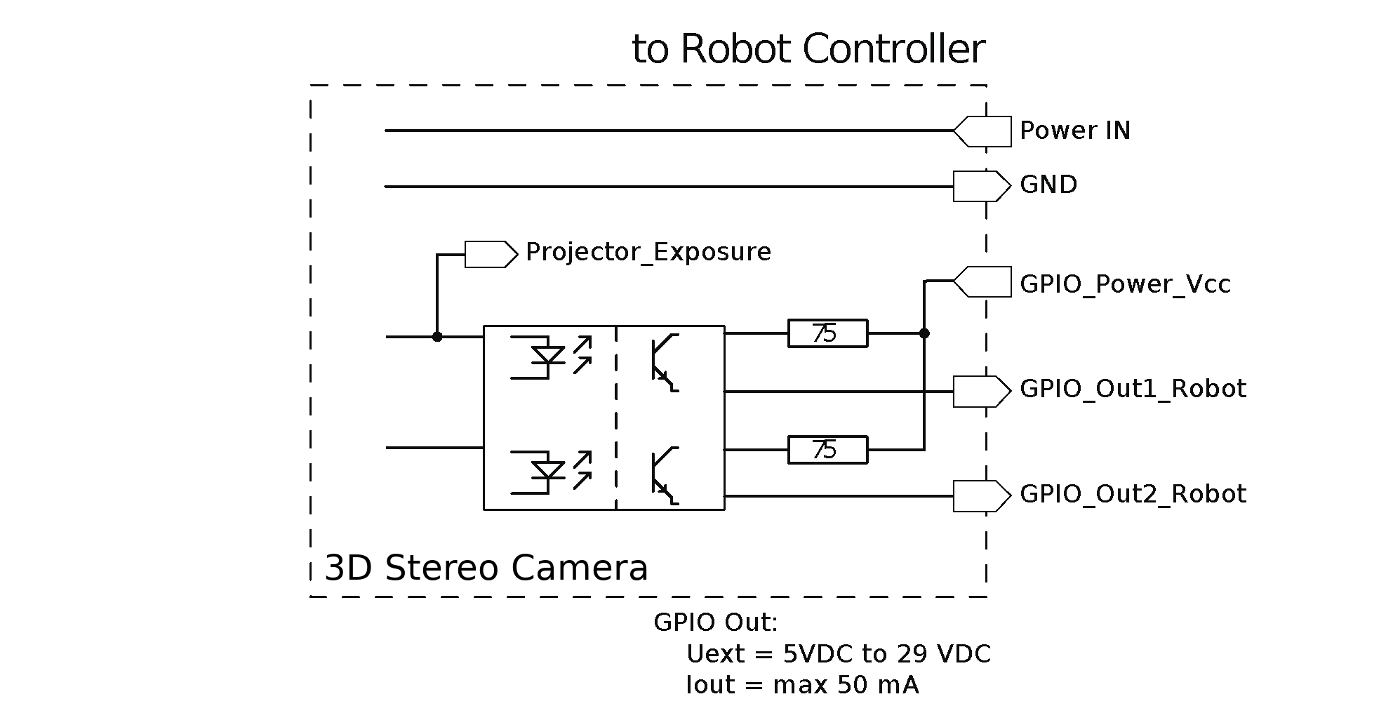
Fig. 5 GPIO circuitry and specifications