Setting Up External Trigger And Flash Control
To set up external trigger and flash control, following things are required:
- mvBlueFOX-1xx or mvBlueFOX-2xx with CCD sensor
- Host PC with USB 2.0 interface
- USB 2.0 cable with max. 5m
- Cable for supplying external trigger signal to camera
- Flash with needed cable and power supply
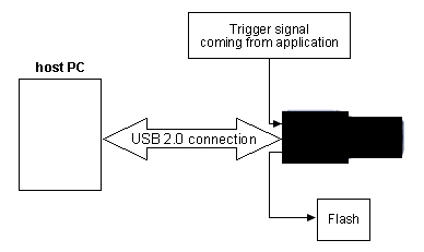
The camera is only connected by USB 2.0 cable to PC. All other signals are connected directly to the camera. Trigger and flash signals are directly controlled by the FPGA, which does the timing in the camera. This makes the trigger and flash control independent from CPU load of host PC or temporary USB 2.0 interrupts.
Trigger control
External trigger signal resets the image acquisition asynchronously to any other timing so that reaction delay is such short that it can be ignored. If a delay between trigger signal and starting integration is needed, it can be defined. By default it is set to 0 us.
Flash control
Signal for flash control is immediately set as soon as image integration begins. If a delay is needed it can be defined. By default this delay is set to 0.
Connection
External trigger signal
Signal for triggering image acquisition must be connected to digital input on backside of the mvBlueFOX on the "D-Sub 9-pin connector" (see product manual https://www.balluff.com/en-de/online-manuals-mv). You can choose either input IN0 (pin 6 and 1) or IN1 (pin 9 and 4) for triggering.
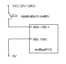
Schematic shows how to fit application's switch to camera's digital input. External trigger signal must be in following conditions:
- TTL (5 V): High min. 3 V, Low max. 1 V
- PLC (24 V): High min. 12 V, Low max. 10 V
Application's switch can be a mechanical one any light barrier or some kind of encounter.
- Note
- Depending on used switch it might be necessary to use a pull-up or pull-down resistor so that camera input can recognize signal correctly.
- See also
- "Characteristics of the digital inputs" in the product manual (https://www.balluff.com/en-de/online-manuals-mv)
To test the general trigger functionality, please follow these steps:
- Select the "Acquisition Mode" "Continuous".
- Click on "Acquire".
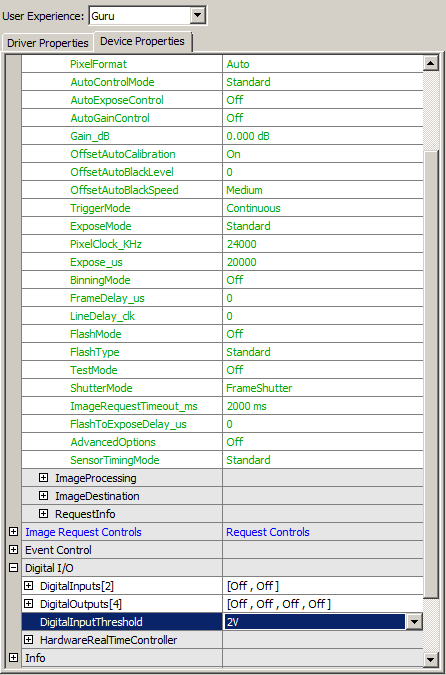
- Set the "TriggerMode" to "OnHighLevel".
- Set the "TriggerMode" to "DigitalInputThreshold" to e.g. 2V.
- Connect a standard power supply with e.g. 5 V (higher than the value of "DigitalInputThreshold") to pin 1 (-) and pin 6 (+)
As long as the power supply is connected, you can see a live preview. If you disconnect the power supply the live preview should stop. If this is working the trigger input works.
External flash signal
For supplying flash with control signal use any digital output Out0 (pin 7 and 2) or Out1 (pin 8 and 3) on 9 pin D-Sub connector.
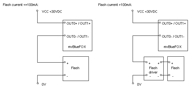
If current needed for flash is below 100 mA you can connect flash directly to camera outputs. If it is higher, you have to use an additional driver for controlling the flash, which provides the higher current.
- Note
- Depending on used flash driver it could be necessary to use pull-up or pull-down resistors so that driver can recognize the signal correctly.
- See also
- "Characteristics of the digital outputs" in the product manual (https://www.balluff.com/en-de/online-manuals-mv)
By default camera is running free. This means, it uses its own timing depending on set pixel clock, exposure time and shutter mode.
Configuring An External Trigger Signal
To let the camera acquire images only with an external trigger signal you must change the "TriggerMode" to the mode suitable to your application:
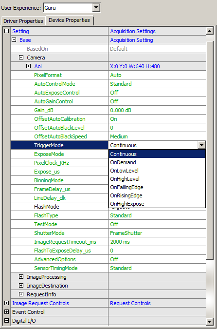
| Mode | Description |
| Continuous | Free running, no external trigger signal needed. |
| OnDemand | Image acquisition triggered by command (software trigger). |
| OnLowLevel | As long as trigger signal is Low camera acquires images with own timing. |
| OnHighLevel | As long as trigger signal is High camera acquires images with own timing. |
| OnFallingEdge | Each falling edge of trigger signal acquires one image. |
| OnRisingEdge | Each rising edge of trigger signal acquires one image. |
| OnHighExpose | Each rising edge of trigger signal acquires one image, exposure time corresponds to pulse width. |
| OnLowExpose | Each falling edge of trigger signal acquires one image, exposure time corresponds to pulse width. |
| OnAnyEdge | Start the exposure of a frame when the trigger input level changes from high to low or from low to high. |
Now, define on which pin the trigger signal is connected to.
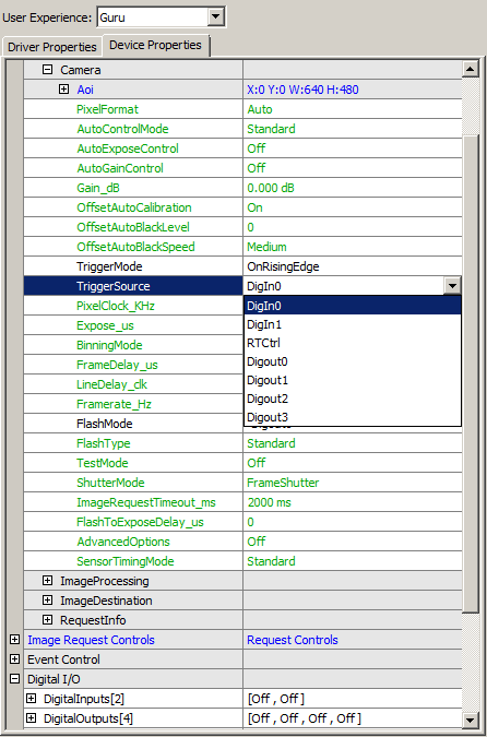
Choose either "DigIn0" if signal is connected to "IN0" or DigIn1 if signal is connected to IN1. In general entry "RTCtrl" is not useful in this case because triggering would be controlled by the HRTC("Hardware Real-Time Controller")(see product manual https://www.balluff.com/en-de/online-manuals-mv) which is not described here and also not necessary.
Depending on voltage level you are using for trigger signal you must choose the "DigitalInputThreshold":
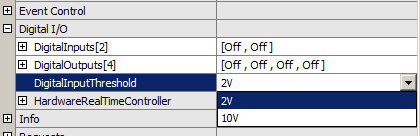
In case of TTL choose 2V and in case of PLC choose 10V.
Now, the image acquisition runs corresponding to external trigger signal and trigger mode. You will see the acquired images on the left part of the window. Preview will be updated in frequency of external trigger.
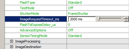
The program knows a timeout period within at least one trigger signal must be provided to the camera. If no trigger signal comes within this time, no image is acquired and an error is set (error count increases). So be sure to set this timeout period to a value, which is long enough to receive at least one trigger signal. You can set this value in "ImageRequestTimeout_ms" property:
Configuring A Flash Signal
To activate flash control signal set "FlashMode" to the output you connected flash or flash driver to:
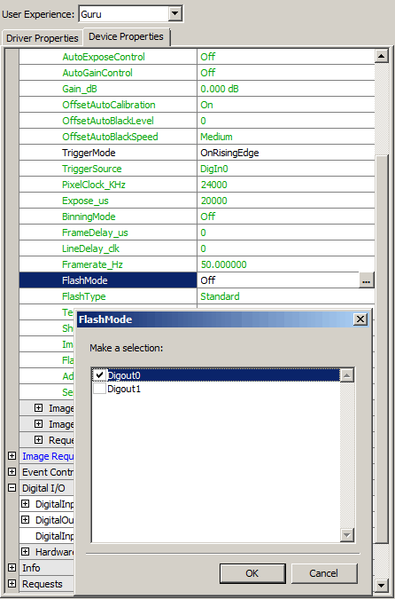
Since this mode is activated each image acquisition will generate the flash signal. This generation is independent from used trigger mode. Flash signal is directly derived from integration timing.
This means that if no "FlashToExposedToLightDelay" is set flash signal will rise as soon as integration starts and fall when integration is finished. The pulse width cannot be changed. So you can be sure that integration takes place when trigger signal is high.
Working With The Hardware Look-Up-Table (LUT)
There are two parameters which handles the pixel formats of the camera:
- "Setting → Camera → PixelFormat" defines the pixel format used to transfer the image data into the target systems host memory.
- "Setting → ImageDestination → PixelFormat" defines the pixel format of the resulting image (which is kept in memory by the Impact Acquire framework).
If both formats are set to "Auto", 8 bit will be used.
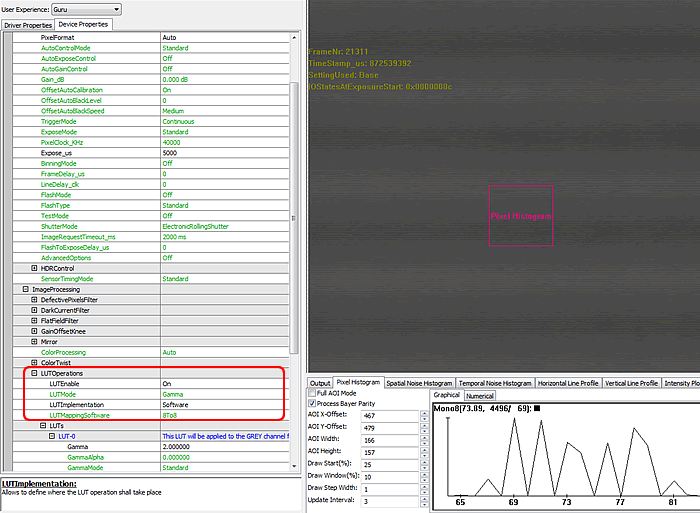
If you set "LUTImplementation" to "Software" in "Setting → ImageProcessing → LUTOperations", the hardware Look-Up-Table (LUT) will work with 8 bit data ("LUTMappingSoftware = 8To8"). Using Gamma functions you will see gaps in the histogram:
If you set "LUTImplementation" to "Hardware" in "Setting → ImageProcessing → LUTOperations", the hardware Look-Up-Table (LUT) will work with 10 bit data inside the camera and converts the data to 8 bit for output ("LUTMappingHardware = 10To8"). Now, there will be no gaps in the histogram:
