Working With Camera Descriptions
Certain capture device (e.g. frame grabber) can process data from a wide range of imaging devices (e.g. cameras). However, in order to interpret the incoming data from an imaging device correctly, the capture device needs to be given a certain amount of information about the structure of the video signal.
The Impact Acquire interface addresses this necessity by the introduction of so called "camera descriptions". A "camera description" is a certain set of parameters that should enable the capture device to cope with the incoming image data to reconstruct a correct image from the imaging device in the memory of the host system. For instance, this information may contain information whether the image is transmitted as a whole or if it's transmitted as individual blocks (e.g. when dealing with interlaced cameras) that need to be reconstructed in a certain way to form the complete image.
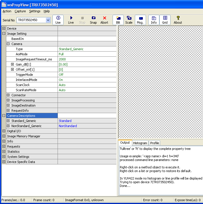
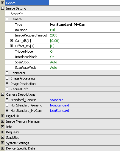
Each capture device will support different sets of parameters. For example some capture devices will only be able to capture image data from standard video source such as a PAL or NTSC compliant camera, while others might only be capable to acquire data from digital image source such as CameraLink® compliant cameras. To reflect these device specific capabilities "camera descriptions" have been grouped into different base classes. See e.g. mvIMPACT::acquire::CameraDescriptionStandard (replace by the syntax matching your preferred language) to find out how the basic structure of these objects look. Which basic "camera description" classes are supported by an individual device can be seen directly after the device has been initialised by looking in the "camera description" list. By default this list will contain one description for each supported basic family:
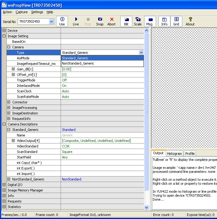
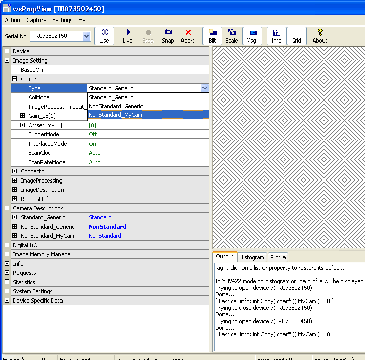
To select a certain camera description to be used to prepare the capture device for the expected data the property "Type" under "Image Settings → Camera" can be modified. Here every available set of camera parameters will be listed:
Now, when a camera is connected, that differs in one or more parameters from the default offered by one of the available base classes and no special description for the imaging device in question is available a new matching description must be generated.
- Note
- It's also possible to modify one of the standard descriptions to adapt the parameter set to the used imaging device, but this method is not recommend as this would define something to be "standard", which in fact is not. Therefore it is not possible to store the standard descriptions permanently. It is, however, possible to modify and work with the changed parameters, but these changes will be lost once the device is closed.
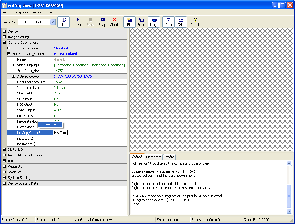
The recommended way of adapting an imaging source to a capture device is to create a new description for a imaging device that does not completely fall into one of the offered standard descriptions. The first thing to decide when creating a new camera description is to which existing description offers the closest match for the new description. Once this has been decided a copy of this description can be created with an arbitrary name (that must be unique within the family the description is created from). Under ImpactControlCenter this can be achieved by
- typing the new name in the parameter edit control right of the "Copy" method of the camera description to create the copy from.
- Afterwards, press
ENTERto commit the new name and then the "Copy" method can be invoked - by right-clicking on the name of the function and
- selecting "Call" from the popup menu:
Afterwards, the newly created camera description will be added to the list of existing ones. Its parameters at this point will match the parent description (the one the "Copy" method was executed from) completely.
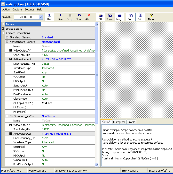
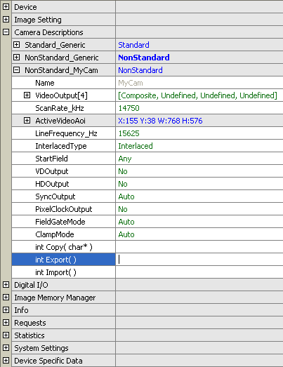
Now, the reason for creating a new camera description was that the parameters in the existing description didn't exactly match the connected imaging device. Therefore, the next step would probably be to modify some of the parameters. Once this has been done (or before) the newly created description can be selected via the property "Type" under "Image Settings → Camera":
- Note
- A new camera description will NOT be stored permanently by default. In order to make this description available the next time the capture device is initialised, the newly created description must be exported via a function call.
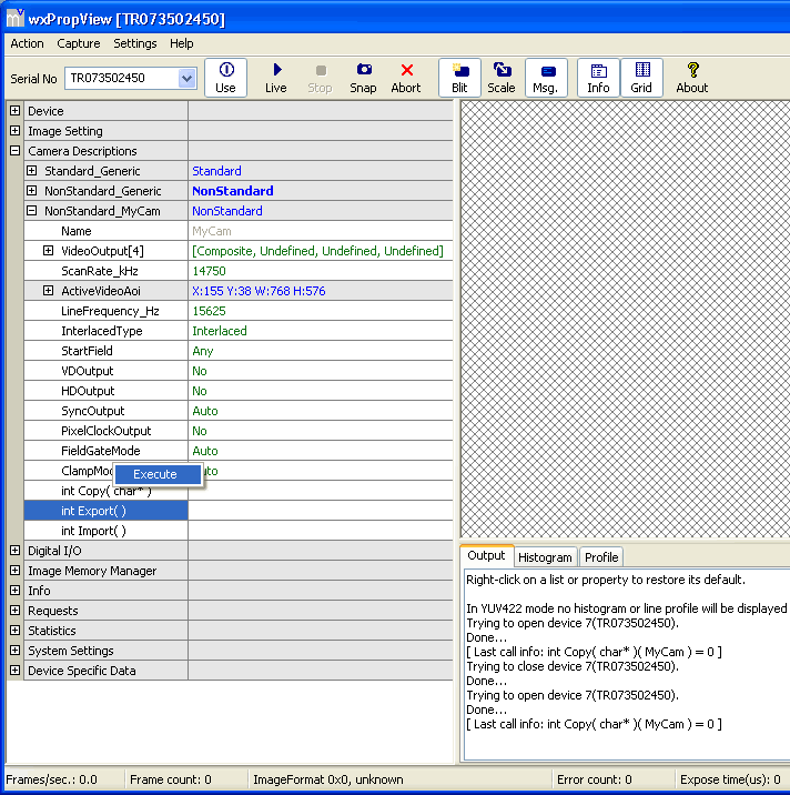
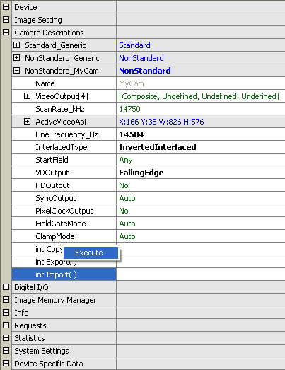
To store a camera description permanently the "Export" method of the new camera description must be invoked. The method does not require any parameters so it can be executed directly by right-clicking on the name of the function and selecting "Execute" from the popup menu:
As a direct result the modified settings will become the new default values of this particular camera description. ImpactControlCenter indicates this by displaying all values belonging to the description in green now:
- Note
- Again please note, that this will NOT work for one of the standard camera descriptions. Whenever the user tries to export one of these, the error DMR_EXECUTION_PROHIBITED will be returned.
When exporting a camera description a file in XML format will be written to disk. On Windows® camera descriptions will be stored under "%PUBLIC%/Documents/Balluff/ImpactAcquire/CameraFiles" or "%MVIMPACT_ACQUIRE_DATA_DIR%\CameraFiles" which will point to the same folder. On Linux® this directory will be "/opt/ImpactAcquire/data/camerafiles" while under other platforms these files will end up in the current working directory.
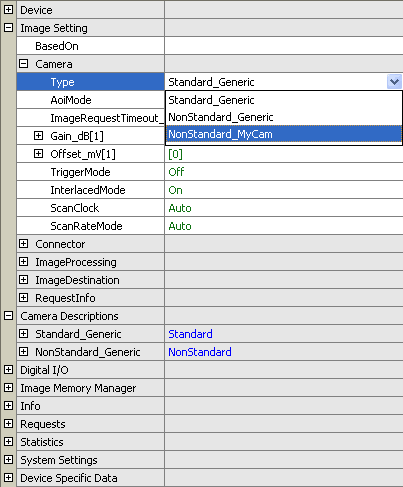
Now, when closing and re-opening a device only the default camera descriptions an the one selected before settings have been saved will appear in the list of camera descriptions. This is to save memory. However, all detected camera descriptions will be available via the property "Type" under "Image Settings → Camera":
Once a description is selected, that hasn't been in the list of camera descriptions before, it will be created and thus will become available for modifications again:
Again: For a different camera a new description should be generated, to operate complex cameras in different modes, a either a new description can be generated or an existing one can be modified.
After a camera has been modified the "Import" method can be used to fall back to the values stored in the camera description file:
This will restore the default settings for this description:
Configuring An Unknown CameraLink Or SDI Camera
If you need a camera description of an unknown CameraLink or SDI camera, ImpactControlCenter supports you with three properties, which can be found in "Info → Camera":
- DataCycleCounterLine0
- DataCycleCounterLine1
- LineCounter
For line scan cameras, the property DataCycleCounterLine0 is enough to know.
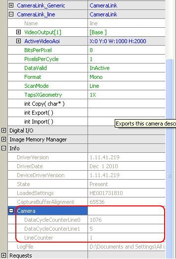
For area scan cameras, you will need all three properties.
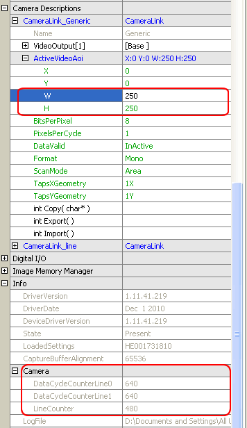
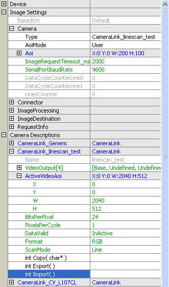
You can take the information in "Info → Camera" to enter the values in "Camera Descriptions". (The figures 37 and 38 are showing CameraLink examples with default values in "Camera Descriptions". The values from "Info → Camera" are not entered yet.)
- Note
- To get the current values of the properties mentioned above you have to "Acquire" a "SingleFrame" first!
Basic Trigger Techniques In CameraLink Systems
Area Scan Cameras
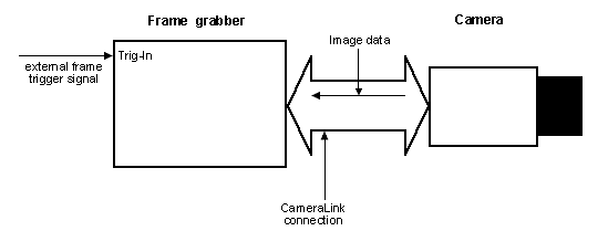
Mode 1: Frame grabber is triggered, free running camera
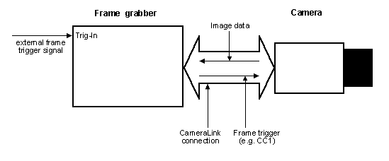
Mode 2: Camera is triggered
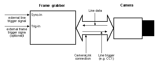
Line Scan Cameras
Mode 1: Camera is triggered by frame grabber
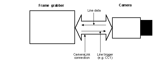
Mode 2: External trigger signal triggers camera
Triggering With mvHYPERION
Area Scan Cameras
Mode 1
In this mode, there is no change in the "Digital I/O" interface necessary.
Now, please follow these steps to run Mode 1 with mvHYPERION:
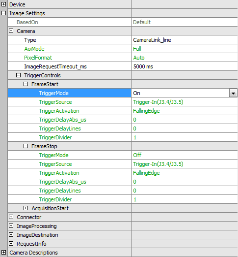
- In "Image Setting → Camera → TriggerControls → Frame Start" set "TriggerMode" to "On".
- Choose the "TriggerSource" input (normally "Trigger-In").
- Choose the "TriggerActivation" according to the application (e.g. "FallingEdge", "RisingEdge", etc.).
In order to that the camera will send an image stream continuously and the next image after a trigger event will be acquired.
Mode 2
In this mode, there is no setup in "TriggerControls" necessary ("TriggerMode" = "Off").
Now, please follow these steps to run Mode 2 with mvHYPERION:
- In "Digital I/O" set "ControlMode" to "PulseStartConfiguration".
-
Now, set the wanted mode of the used CameraLink signal (normally "DigitalOutputs → CC1"), which is used for triggering "TriggerSource" input (normally "Trigger-In"):
- "SinglePulse": On the basis of "PulseStartConfiguration" a signal is created and given to the camera for triggering. Delay time and pulse width can be defined.
- "PassThrough": The signal of the chosen input will be negated in timing and pulse width or not passed to the camera.
-
In "PulseStartConfiguration" set the PulseStartTrigger to "DigitalSignal":
- Set "DigitalSignal" to the wished input (normally: "Trigger-In").
- If the signal happens too fast, you can divide the trigger frequency with the "TriggerDivider".
- "TriggerMoment" shows the starting time with falling or rising edge.
Now, after a external trigger signal on the trigger input of the frame grabber, a trigger signal is generated on the CameraLink connection ("CC1") and passed to the camera. In order to that, the camera acquires an image and sends it to the frame grabber. You do not need a trigger on the frame grabber for the image acquisition given that the frame grabber waits for the next image.
Line Scan Cameras
Mode 1
In this mode, there is no setup in "TriggerControls" necessary ("TriggerMode" = "Off").
Now, please follow these steps to run Mode 1 with mvHYPERION:
-
In "Digital I/O" set the mode to "SinglePulse" of the used CameraLink signal (normally "DigitalOutputs → CC1"), which is used for triggering and
- define "Priority", "Delay_us" and "Width_us" (pulse width).
- Afterwards, set the "PulseStartConfiguration" to "PulseStartConfiguration0".
-
In "PulseStartConfiguration"
- set the PulseStartTrigger to "Periodically".
- The Property "Frequency_Hz" defines the line frequency, which is passed to the camera over "CC1".
Mode 2
"TriggerControls" settings in this mode are optionally.
Following settings in "Digital I/O" are necessary:
-
Now, set the wanted mode of the used CameraLink signal (normally "DigitalOutputs → CC1"), which is used for triggering "TriggerSource" input (normally "Trigger-In"):
- "SinglePulse": On the basis of "PulseStartConfiguration" a signal is created and given to the camera for triggering. Delay time and pulse width can be defined.
- "PassThrough": The signal of the chosen input will be negated in timing and pulse width or not passed to the camera. Please choose "Sync-In" as input. No further settings are necessary.
-
In "PulseStartConfiguration" set the PulseStartTrigger to "DigitalSignal":
- Set "DigitalSignal" to the wished input (normally: "Sync-In").
- If the signal happens too fast, you can divide the trigger frequency with the "TriggerDivider".
- "TriggerMoment" shows the starting time with falling or rising edge.
Now, after a external trigger signal on the sync input of the frame grabber, a trigger signal is generated on the CameraLink connection ("CC1") and passed to the camera. In order to that, the camera acquires an image and sends it to the frame grabber. It is possible to trigger the image acquisition of the frame grabber externally. For this, please do following:
- In "Image Settings → Camera → TriggerControls → Frame Start" set "TriggerMode" to "On".
-
Choose the "TriggerSource" input (normally
"Trigger-In"). - Choose the "TriggerActivation" according to the application (e.g. "FallingEdge", "RisingEdge", etc.).
Per image and frame trigger, the number of lines will be acquired, which were defined in the camera description and the AOI setting before.
Camera Acquisition Techniques
There are different camera acquisition techniques. How you can set them with ImpactControlCenter, which will be shown in the following section.
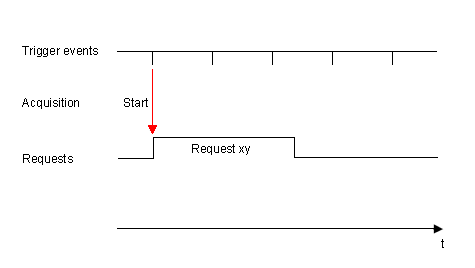
StartTrigger
Directly after the trigger signal the acquisition starts. If you have, for example, a line scan camera and want to acquire 1000 lines, 1000 lines will be acquired. During this time, further trigger signals are ignored.
To use StartTrigger, in ImpactControlCenter you have to
- set "Image Settings → Camera → TriggerControls → FrameStart" to "On",
- select in "FrameStart" the used "TriggerSource" and
- set "Image Settings → Camera → TriggerControls → FrameStop" to "Off".
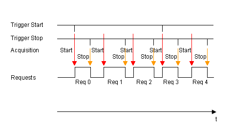
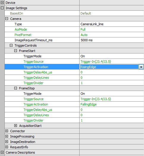
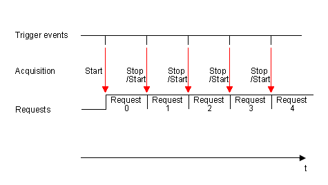
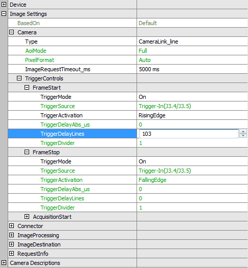
TriggerStartStop
In TriggerStartStop there are two trigger sources, one to start the acquisition and the second trigger event to stop it. Between start and stop, there is at least one line pause. The image height is affected by the stop event.
To use TriggerStartStop, in ImpactControlCenter you have to
- set "Image Settings → Camera → TriggerControls → FrameStart" to "On",
- select in "FrameStart" the used "TriggerSource",
- set "Image Settings → Camera → TriggerControls → FrameStop" to "On" and
- select in "FrameStop" the used "TriggerSource".
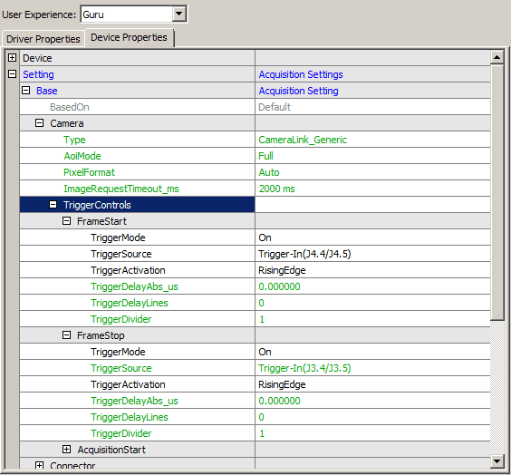
TriggerStartStop - Restart
With "TriggerStartStop - Restart" the first trigger starts the acquisition and following trigger signal stops the previous acquisition and starts the next one.
To use "TriggerStartStop - Restart", in ImpactControlCenter you have to
- set the same parameters in "Image Settings → Camera → TriggerControls → FrameStart" and "Image Settings → Camera → TriggerControls → FrameStop".
- Note
- The image height depends on the trigger frequency.
- trigger period > frame period → image height complete
- trigger period < frame period → image height reduced (line synchronous; next request starts immediately without loss of lines)
- trigger period > frame period → image height complete
TriggerDelay
With TriggerDelay it is possible to specify a delay after the trigger start event.
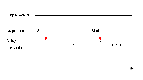
To use TriggerDelay, in ImpactControlCenter you have to
- set in "CameraDescriptions" the "Y" parameter of "ActiveVideoAoi",
Using line scan cameras, the "Y" position specifies the trigger acquisition delay in lines.
Triggering With mvTITAN-CL / mvGAMMA-CL
Area Scan Cameras
Mode 1
In this mode, there is no change in the "Digital I/O" interface necessary.
Now, please follow these steps to run Mode 1:
- In "Camera → TriggerMode" choose the "TriggerMode" (see also: CameraSettingsFrameGrabber and TriggerControl).
- Choose the "TriggerSource" input (normally "Trigger-In").
- Choose the "TriggerActivation" according to the application (e.g. "FallingEdge", "RisingEdge", etc.).
In order to that the camera will send an image stream continuously and the next image after a trigger event on input Trigger-In will be snapped.
Mode 2
In this mode, there is no setup in "Camera" necessary.
Now, please follow these steps to run Mode 2:
- In "Digital I/O → DigitalOutputs" (see also: IOSubSystemFrameGrabber) set "ControlMode" of the used CameraLink signal (normally "DigitalOutputs → CC1") to "SinglePulse".
-
Now, set
- negation in "Polarity".
- delay time in "Delay_us".
- pulse width in "Width_us".
-
In "Digital I/O → DigitalOutputs" set
- "PulseStartEvent" to "Trigger".
- "ImageTrigger" to the wished image acquisition point in time.
Now, after a external trigger signal on the trigger input "Trigger-In" of the frame grabber, a trigger signal is generated on the CameraLink connection ("CC1") and passed to the camera. In order to that, the camera snaps an image and sends it to the frame grabber. You do not need a trigger on the frame grabber for the image acquisition given that the frame grabber waits for the next image.
Line Scan Cameras
Mode 1
In this mode, there is no setup in "Camera" necessary.
Now, please follow these steps to run Mode 1:
-
In "Digital I/O → DigitalOutputs" (see also: IOSubSystemFrameGrabber and PulseStartConfiguration) set
- set "ControlMode" to "RTC". "CC1" should disappear.
- Choose in "PulseStartEvent(line scan)" "Periodically".
- Set "SoftwareSignalPeriod_pclk", which specifies the period of the signal which is passed to the camera.
- Select the CameraLink channel of the signal in "Output" (normally "CC1").
- Set the pulse width in "Width_pclk".
- Set the negation in "Polarity".
In order to that the frame grabber will create a continuous signal with the defined period and it will be sent to the camera via CameraLink. With this signal, the camera acquires lines and sends them to the frame grabber. Per image, the number of lines will be acquired, which were defined in the camera description and the AOI setting before.
Mode 2
Following settings in "Digital I/O" are necessary:
-
In "Digital I/O → DigitalOutputs" (see also: IOSubSystemFrameGrabber and PulseStartConfiguration) set the "PulseStartEvent"
- Choose a "PassThrough" mode to pass through the external trigger signal on "Sync-In" in frequency and pulse width.
- Choose CameraLink output (normally "CC1").
-
Create a new signal via modes "Sync-In RisingEdge" or "Sync-In FallingEdge":
- Choose CameraLink output (normally "CC1").
- Set the pulse width in "Width_pclk".
- Set the negation in "Polarity".
- If the line trigger signal happens too fast, you can divide the trigger frequency with the "Dividers".
- "TriggerMoment" shows the starting time with falling or rising edge.
Now, after a external trigger signal on the sync input of the frame grabber, a trigger signal is generated on the CameraLink connection ("CC1") and passed to the camera. In order to that, the camera acquires an image and sends it to the frame grabber. It is possible to trigger the image acquisition of the frame grabber externally. For this, please do following:
- In "Image Settings → Camera → TriggerControls → Frame Start" set "TriggerMode" to "On".
-
Choose the
"TriggerSource"input"Trigger-In".
Per image and frame trigger, the number of lines will be acquired, which were defined in the camera description and the AOI setting before.