Loading...
Searching...
No Matches
Creating acquisition sequences (Sequencer Control)
Introduction
As mentioned in GenICam And Advanced Features section of this manual, the Sequencer Mode is a feature to define feature sets with specific settings. The sets are activated by a user-defined trigger source and event.
- Note
- At the moment, the Sequencer Mode is only available for Balluff/MATRIX VISION cameras with CCD sensors and Sony's CMOS sensors. Please consult the "Device Feature and Property List"s to get a summary of the actually supported features of each sensor.
The following features are currently available for using them inside the sequencer control:
| Feature | Note | Changeable during runtime |
| BinningHorizontal | - | |
| BinningVertical | - | |
| CounterDuration | Can be used to configure a certain set of sequencer parameters to be applied for the next CounterDuration frames. | since Firmware version 2.15 |
| DecimationHorizontal | - | |
| DecimationVertical | - | |
| ExposureTime | since Firmware version 2.15 | |
| Gain | since Firmware version 2.15 | |
| Height | since Firmware version 2.36 | |
| OffsetX | since Firmware version 2.35 | |
| OffsetY | since Firmware version 2.35 | |
| Width | since Firmware version 2.36 | |
| mvUserOutput | - | |
| UserOutputValueAll | - | |
| UserOutputValueAllMask | - | |
| Multiple conditional sequencer paths | - |
The Sequencer Control uses Counter And Timer Control Counter1 to work. If you already preset Counter1 and you save a new acquisition sequence, the settings of Counter1 will be overwritten.
- Note
- Configured sequencer programs are stored as part of the User Sets like any other feature.
Creating a sequence using the Sequencer Control in ImpactControlCenter
In this sample, we define an acquisition sequence with five different exposure times on the device whereby the last step should be repeated five times. We also activate the digital outputs 0..3 to the sets accordingly - this, for example, can be used as flash signals. All the configuration is done on the device itself so after finishing the configuration and starting the acquisition the device itself will apply the parameter changes when necessary. The host application only needs to acquire the images then. This results in a much faster overall frame rate compared to when applying these changes on a frame to frame basis from the host application.
- 1000 us
- 5000 us
- 10000 us
- 20000 us
- 50000 us (5x)
This will result in the following flow diagram:
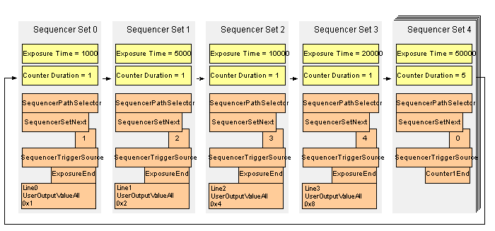
As a consequence the following exposure times will be used to expose images inside an endless loop once the sequencer has been started:
- Frame 1: 1000 us
- Frame 2: 5000 us
- Frame 3: 10000 us
- Frame 4: 20000 us
- Frame 5: 50000 us
- Frame 6: 50000 us
- Frame 7: 50000 us
- Frame 8: 50000 us
- Frame 9: 50000 us
- Frame 10: 1000 us
- Frame 11: 5000 us
- Frame 12: 10000 us
- ...
So the actual sequence that will be executed on the device later on will be like this
while( sequencerMode == On )
{
  take 1 image using set 0
  take 1 image using set 1
  take 1 image using set 2
  take 1 image using set 3
  take 5 images using set 4
}
- There are 2 C++ examples called GenICamSequencerUsage and GenICamSequencerParameterChangeAtRuntime that show how to control the sequencer from an application. They can be found in the
Examplessection of the Impact Acquire C++ API
The following steps are needed to configure the device as desired:
- Note
- This is the SFNC way how to create an acquisition sequence and consequently how you have to program it. However, ImpactControlCenter offers a wizard to define an acquisition sequence in a much easier way.
-
First, switch into the "Configuration Mode": "Sequencer Configuration Mode" = "On". Only then the sequencer on a device can be configured.
Figure 2: ImpactControlCenter - Sequencer Configuration Mode = On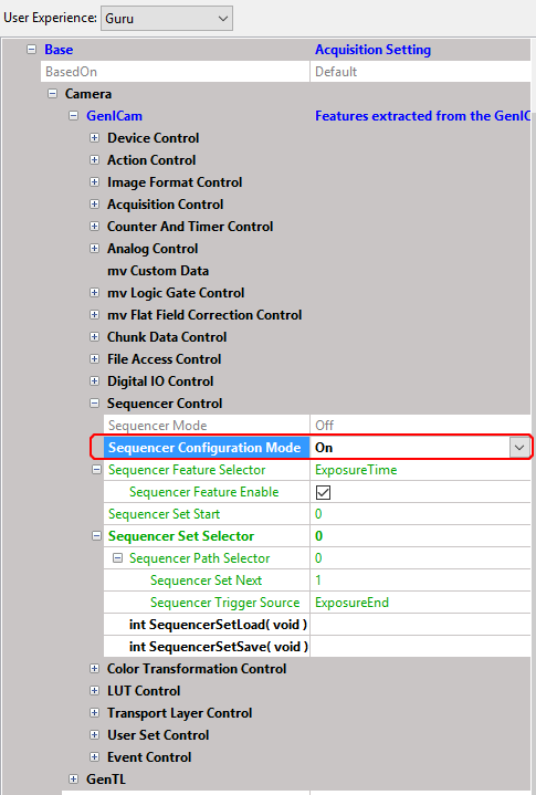
- Set the "Sequencer Feature Selector", if it is not already active (pink box, figure 3): "Sequencer Feature Selector" = "ExposureTime" and "Sequencer Feature Enable" = "1".
- Set the "Sequencer Feature Selector" for the duration counter (pink box, figure 4): "Sequencer Feature Selector" = "CounterDuration" and "Sequencer Feature Enable" = "1".
- Set the "Sequencer Feature Selector" for using the UserOutputs: "Sequencer Feature Selector" = "mvUserOutput" and "Sequencer Feature Enable" = "1".
-
Then, each sequencer set must be selected by the "Sequencer Set Selector" (orange box, figure 3): "Sequencer Set Selector" = "0".
Figure 3: ImpactControlCenter - Sequencer set 0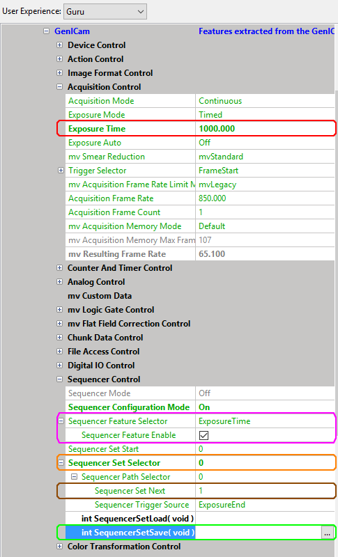
- Set the following sequencer set using "Sequencer Set Next" (brown box, figure 3): "Sequencer Set Next" = "1".
- Set the "Exposure Time" (red box, figure 3): "Exposure Time" = "1000".
- Finally, save the "Sequencer Set" (green box, figure 3): "int SequencerSetSave()". This ends the configuration of this sequencer set and all the relevant parameters have been stored inside the devices RAM.
- Set the "UserOutputValueAllMask" (purple box, figure 4) to a suitable value. In this case we want to use all UserOutputs, so we set it to "0xf".
-
Set the "UserOutputValueAll" (red box, figure 4): "UserOutputValueAll" = "0x1".
Figure 4: ImpactControlCenter - DigitalIOControl - Set UserOutputValueAll of Line3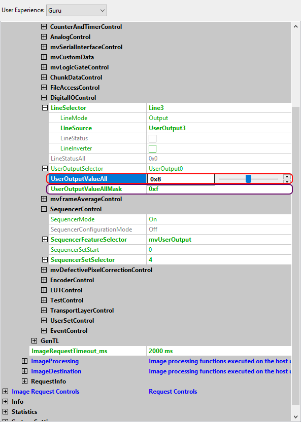
- Repeat these steps for the following 3 sequencer sets (Exposure Times 5000, 10000, 20000; UserOutputValueAll 0x2, 0x4, 0x8).
- For the last sequencer set, set the desired sequencer set with "Sequencer Set Selector" (orange box, figure 5): "Sequencer Set Selector" = "4".
-
Set the following sequencer set with "Sequencer Set Next" and trigger source with "Sequencer Trigger Source" (brown box, figure 5):
"Sequencer Set Next" = "0". This will close the loop of sequencer sets by jumping from here back to the first one.
"Sequencer Trigger Source" = "Counter1End". -
Set the "Exposure Time" (red box, figure 5): "Exposure Time" = "50000".
Figure 5: ImpactControlCenter - Sequencer set 4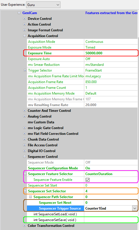
-
Set the "Counter Duration" in "Counter And Timer Control" (red box, figure 6): "Counter Duration" = "5".
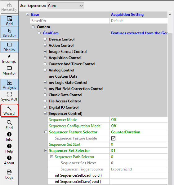
Figure 6: ImpactControlCenter - "Sequencer Mode" = "On"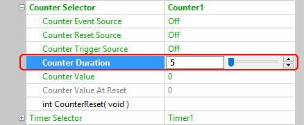
- As there are only four UserOutputs we decided not to show sequencer set "4" on the output lines.
- Finally, save the "Sequencer Set" (green box, figure 3): "int SequencerSetSave()".
- Leave the "Configuration Mode" (red box, figure 4: "Sequencer Configuration Mode" = "Off".
-
Activate the "Sequencer Mode" (red box, figure 4): "Sequencer Mode" = "On".
Figure 7: ImpactControlCenter - "Sequencer Mode" = "On"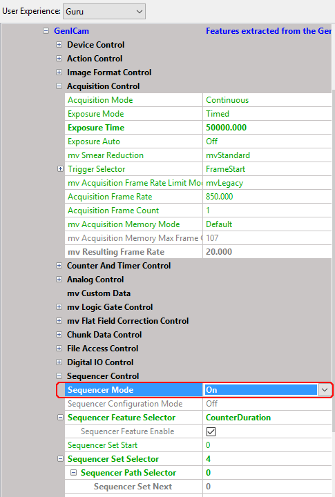
- Note
- The "Sequencer Mode" will overwrite the current device settings.
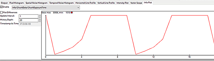
You will now see that the sequencer sets are processed endlessly. Via the chunk data (activate chunk data via "Setting → Base → Camera → GenICam → Chunk Data Control" - activate "Chunk Mode Active"), the "Info Plot" of the analysis grid can be used to visualize the exposure times:
Adapting the active time on the output lines via logic gates
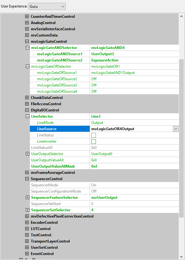
If you do not want to see the whole active time of a given sequencer set but only the exposure time of a given sequencer set, you can combine your signal with the logic gates in mvLogicGateControl. Figure 8 shows sample settings of Line3:
This produces the following output on the output lines:
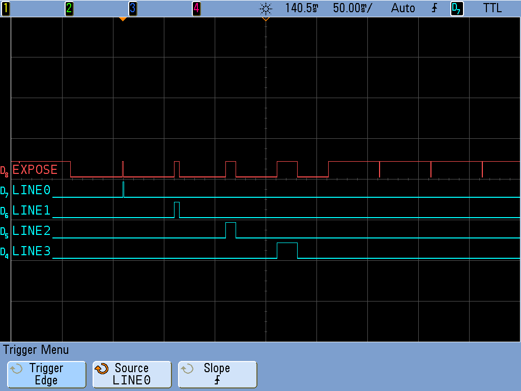
These signals could be used as flash signals for separate sequencer sets.
You can program this as follows:
#include <mvIMPACT_CPP/mvIMPACT_acquire_GenICam.h>

GenICam::DigitalIOControl dio = new GenICam::DigitalIOControl(pDev);
dio.userOutputValueAllMask.write( 0xF );
dio.userOutputValueAll.write( 0x1 ); // 0x2, 0x4, 0x8, 0x0

GenICam::mvLogicGateControl mvlgc = new GenICam::mvLogicGateControl(pDev);
mvlgc.mvLogicGateANDSelector.writeS("mvLogicGateAND1");
mvlgc.mvLogicGateANDSource1.writeS("UserOutput0");
mvlgc.mvLogicGateANDSource2.writeS("ExposureActive");
mvlgc.mvLogicGateORSelector.writeS("mvLogicGateOR1");
mvlgc.mvLogicGateORSource1.writeS("mvLogicGateAND1Output");
mvlgc.mvLogicGateORSource2.writeS("Off");
mvlgc.mvLogicGateORSource3.writeS("Off");
mvlgc.mvLogicGateORSource4.writeS("Off");

dio.lineSelector.writeS("Line0");
dio.lineSource.writeS("mvLogicGateOR1Output");

// To output the UserOutputs directly on the output lines would be like this:
// dio.lineSource.writeS("UserOutput0");
Using the Sequencer Control wizard
Since version 2.18.0 ImpactControlCenter offers a wizard for the Sequencer Control usage:
The wizard can be used to get a comfortable overview about the settings of the sequence sets and to create and set a sequence sets in a much easier way:
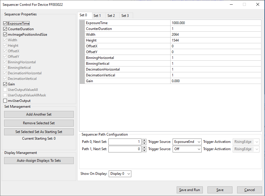
Just
- select the desired properties,
- select the desired Set tabs,
- set the properties in the table directly, and
- "Auto-Assign Displays To Sets", if you like to show each sequence set in a different display.
Do not forget to save the settings at the end.
Working with sequencer paths
- Since
- Firmware version 2.28.0
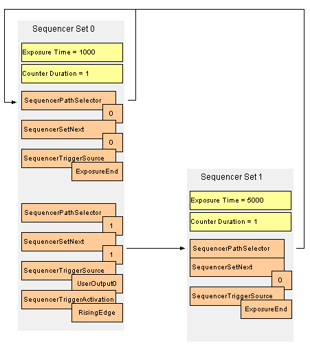
It is possible to define sets with a maximum of two active paths. The following diagram shows that two paths are defined in "Set 0". "Path 0" ("SequencePathSelector = 0") is the "standard" path that in this configuration loops and "Path 1" ("SequencePathSelector = 1") will jump to "Set 1" after it is activated via a "RisingEdge" ("SequencerTriggerActivation = RisingEdge") signal at "UserOutput0" ("SequencerTriggerSource = 0"). "UserOutput0" can be connected, for example, to one of the digital input lines of the camera:
There are some specifications concerning the sequencer path feature:
- A path is inactive as soon as the "SequencerTriggerSource" is Off.
- If none of the paths are triggered or both parts are inactive, the sequencer will remain in the current set.
- If both paths were triggered, the path with the trigger that happened first, will be followed.
- As the next sequencer set parameters (like ExposureTime) need to be prepared beforehand, the set sequence might not seem straight forward at first glance. The sequencer will always need one frame to switch to the new set; this frame will be the already prepared set.
Programming a sequence with paths using the Sequencer Control
First the sequencer has to be configured.
  #include <mvIMPACT_CPP/mvIMPACT_acquire_GenICam.h>

  GenICam::SequencerControl sc = new GenICam::SequencerControl( pDev );
  GenICam::AcquisitionControl ac = new GenICam::AcquisitionControl( pDev );
  TDMR_ERROR result = DMR_NO_ERROR;

  // general sequencer settings
  sc.sequencerMode.writeS( "Off" );
  sc.sequencerConfigurationMode.writeS( "On" );
  sc.sequencerFeatureSelector.writeS( "ExposureTime" );
  sc.sequencerFeatureEnable.write( bTrue );
  sc.sequencerFeatureSelector.writeS( "CounterDuration" );
  sc.sequencerFeatureEnable.write( bFalse );
  sc.sequencerFeatureSelector.writeS( "Gain" );
  sc.sequencerFeatureEnable.write( bFalse );
  sc.sequencerSetStart.write( 0 );

  // set0
  sc.sequencerSetSelector.write( 0LL );
  ac.exposureTime.write( 1000 );
  // set0 path0
  sc.sequencerPathSelector.write( 0LL );
  sc.sequencerTriggerSource.writeS( "ExposureEnd" );
  sc.sequencerSetNext.write( 0LL );
  // set0 path1
  sc.sequencerPathSelector.write( 1LL );
  sc.sequencerTriggerSource.writeS( "UserOutput0" );
  sc.sequencerTriggerActivation.writeS( "RisingEdge" );
  sc.sequencerSetNext.write( 1LL );
  // save set
  if( ( result = static_cast<TDMR_ERROR>( sc.sequencerSetSave.call() ) ) != DMR_NO_ERROR )
  {
    std::cout << "An error was returned while calling function '" << sc.sequencerSetSave.displayName()
              << "' on device " << pDev->serial.read()
              << "(" << pDev->product.read() << "): "
              << ImpactAcquireException::getErrorCodeAsString( result ) << endl;
  }

  // set1
  sc.sequencerSetSelector.write( 1LL );
  ac.exposureTime.write( 5000 );
  // set1 path0
  sc.sequencerPathSelector.write( 0LL );
  sc.sequencerTriggerSource.writeS( "ExposureEnd" );
  sc.sequencerSetNext.write( 0LL );
  // set1 path1
  sc.sequencerPathSelector.write( 1LL );
  sc.sequencerTriggerSource.writeS( "Off" );
  // save set
  if( ( result = static_cast<TDMR_ERROR>( sc.sequencerSetSave.call() ) ) != DMR_NO_ERROR )
  {
    std::cout << "An error was returned while calling function '" << sc.sequencerSetSave.displayName()
              << "' on device " << pDev->serial.read()
              << "(" << pDev->product.read() << "): "
              << ImpactAcquireException::getErrorCodeAsString( result ) << endl;
  }

  // final general sequencer settings
  sc.sequencerConfigurationMode.writeS( "Off" );
  sc.sequencerMode.writeS( "On" );
Then it can later be triggered during runtime.
  GenICam::DigitalIOControl dic = new GenICam::DigitalIOControl( pDev );
  dic.userOutputSelector.write( 0 );
  dic.userOutputValue.write( bTrue );
  dic.userOutputValue.write( bFalse );
This will set an internal event that will cause the sequencer to use set0-path1 at the next possible time, i.e. the next time we are in set0.
There is a C++ example called GenICamSequencerUsageWithPaths that shows how to control the sequencer with paths from an application. It can be found in the Examples section of the C++ interface documentation (Impact Acquire C++ API)