| A/D reference | Upper threshold of video signal to be digitized. All values above this limit value are digitized to 255. Increasing the reference level results in contrast deterioration and vice versa. |
| ADC | Analog-to-digital converter (A/D converter). |
| API | Application programming interface (API). The standard API for Balluff/MATRIX VISION products is called Impact Acquire. |
| Base address | Starting address from which the memory or register are inserted. |
| Bpp | Bits per pixel |
| Bus | A group line via which the various parts of the computer communicate with one another. |
| BusyBox | Configurable monolithic application including shell and other useful command-line tools - often called the "swiss army knife" for embedded systems. Even desktop distributions are sometimes relying on BusyBox due to its robustness. Please see http://www.busybox.net for details. |
| CCIR | Comité Consulatif International of the Radio Communications European video standard for 50 Hz gray scale. |
| CIFS | Common Internet file system (CIFS) replaced Samba in 2006. It gets rid of NetBIOS packets an introduced Unix features like soft/hard links and allows larger files. |
| Clamp signal | Clamp signal means, that a AC coupled video signal is clamped on the porch to get a signal transfer with less noise and independent from the d.c. voltage portion. |
| CPU | Central processing unit aka processor. |
| DAC | Digital to analog converter (D/A converter). |
| Defaults | Standard system settings. |
| DHCP | Dynamic Host Configuration Protocol (DHCP). DHCP is a protocol used by networked devices (clients) to obtain various parameters necessary for the clients to operate in an Internet Protocol (IP) network. |
| Digital I/O | Digital inputs and outputs. |
| External trigger | External event used to initiate image capture. |
| False colors | Colors are assigned to gray scale via a look-up table. This allows even small gray scale differences can be displayed clearly. |
| GDB | GDB, the GNU Project debugger. |
| GenICam | GenICam stands for GENeric programming Interface for CAMeras. 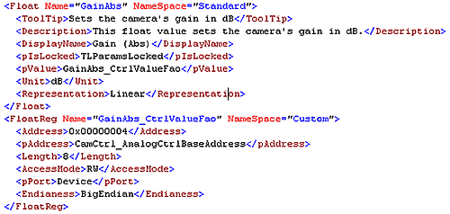
Excerpt of a GenICam™ description file (in XML) For further information on this topic please have a look at
|
| GenTL | GenTL is the transport layer interface for cameras, acquiring images from the camera, and moving them to the user application. |
| Gigabit Ethernet (GigE) | The term Gigabit Ethernet (defined by the IEEE 802.3-2008 standard) represents various technologies for transmitting Ethernet frames at a rate of a gigabit per second (1,000,000,000 bits per second). |
| GigE Vision™ | GigE Vision™ is a network protocol defined and administered by the Association for Advancing Automation (A3), designed for the
|
| High Dynamic Range (HDR) | The HDR (High Dynamic Range) mode increases the usable contrast range. This is achieved by dividing the integration time in two or three phases. The exposure time proportion of the three phases can be set independently. Furthermore, it can be set, how many signal of each phase is charged. |
| Horizontal sync | The portion of the analog signal which specifies the line end of the video signal. |
| Host | Here: the PC |
| HRTC | With a Hardware Real-Time Controller (HRTC) built inside the FPGA users can define a PLC like sequence of operating steps to control basic time critical functions like exposure time, image trigger and I/O ports. Timing is hard real-time with sub microsecond high resolution. |
| IDE | a software application that provides comprehensive facilities to computer programmers for software development. An IDE normally consists of a source code editor, a compiler and/or interpreter, build automation tools, and (usually) a debugger. |
| Image refresh rate | Number of transferred images per second. Normally specified in Hz (e.g. 70 Hz) |
| Interrupt | Interrupt signal sent to the processor. The program currently running is interrupted and a predefined function is executed. |
| IPKG | Itsy package management system originally designed for embedded systems. Please have a look at https://en.wikipedia.org/wiki/Ipkg or a more sophisticated documentation at http://buffalo.nas-central.org/index.php "Overview_of_the_ipkg_package_management_system" Balluff distributes all non-firmware, i.e. optional software as ipk packages. |
| IRQ | Interrupt request |
| ISR | Interrupt service routine |
| JFFS2 | JFFS2 is a file system which supports wear leveling.
|
| Link Aggregation (LAG) | Dual-GigE cameras need a network interface card with |
| LLA | Logical link address (LLA) is a type of mechanism to With Linux you have to add LLA as an additional interface. 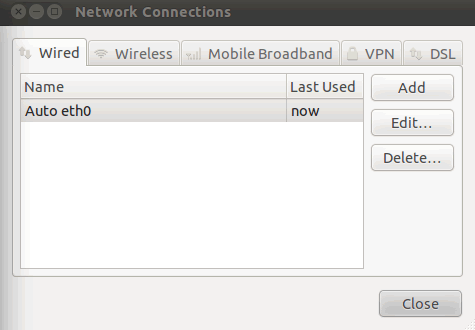
In Wired, you can add interfaces via Add: 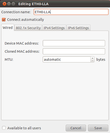
|
In the tab "IPv4 Setting" you have to set "Link-Local Only": 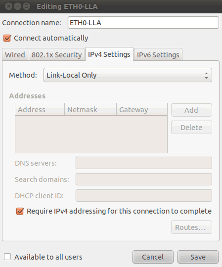
After saving, you will find both connections in the summary: 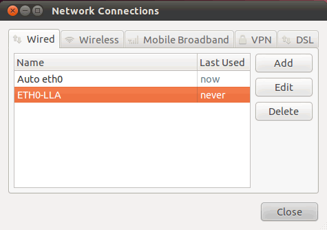
Now, you can select the wished connection using the left mouse button in the "Network Manager" menu. In the LLA case it is just the new created connection: 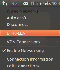
| |
| Look-up table | Table of assignments. Here, new gray scale or colors are normally assigned to gray scale. Look-up tables can, however, also be used for any other math functions. |
| LSB | Least significant bit |
| LUT | Look-up table |
| MAC address | Media Access Control address (MAC address) is a quasi-unique identifier attached to most network adapters (NICs) in computer networking. |
| MTU | Maximum transmission unit (MTU) refers to the size (in bytes) of the largest packet that a given layer of a communications protocol can pass onwards. The default MTU for Ethernet is 1500. The optimum for Gigabit Ethernet is 8000 - 12000. Different MTU settings in the same subnet can cause package losses, i.e. never ever change the MTU unless you know what you're doing. Changing the MTU to other values than 1500 when using file or web services from other computers are almost always a bug. It's save to increase MTU when working in peer-to-peer mode with both devices sharing the same MTU. Please not that few network cards support 16K, most Gigabit Ethernet cards are limited to 9k, some don't support Jumbo Frames (MTU > 1500) at all. |
| Monochrome | A single-color (black and white) image |
| MSB | Most significant bit |
| Impact Acquire | This driver supplied with Balluff products represents The SDK documentation of the Impact Acquire can be found at the manuals section. |
| Netboot | With netboot you can boot a BVS CA-GX camera over network. This is especially useful when several devices share the same pieces of software, i.e. same root file system, which might be subject to change frequently. |
| NFS | Network File System (NFS) is a network file system protocol, allowing clients to access files over LAN. Given that you need a NFS server are uncommon on Windows®, this protocol best fits for Linux-Linux connections. |
| NIC | Network interface card - synonym for network controller. |
| Overlapped / pipelined transfer | By default, the steps exposure and readout out of an image sensor are done one after the other.
Please check the sensor summary. In overlapping mode, the exposure starts the exposure time earlier during readout. 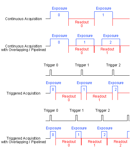
|
| Pixels | Picture element |
| PSE | Power sourcing equipment. The network PoE element that inserts power onto an Ethernet cable. |
| Pseudo colors | Display of gray scale images in false colors. A corresponding color is assigned to a specific gray scale value. |
| Resolution | Number of pixels (horizontal x vertical) |
| ROI/AOI | Region/Area of interest. |
| SFNC | Standard Feature Naming Convention of GenICam.
|
| Shell | In computing, a shell is a piece of software that provides an interface for users. Command-line shells provide a command-line interface (CLI) to the operating system. The primary purpose of the shell is to invoke or "launch" another program; however, shells frequently have additional capabilities such as viewing the contents of directories. |
| Square pixels | Square-shaped pixels (height-width ratio 1:1) |
| True color | 24-bit true color; 16.7 million colors |
| USB3 Vision™ | A closed source framework, defined and administered by the Association for Advancing Automation (A3), for transmitting video and related control data over USB 3. Sometimes U3V is used as an acronym. |
| UDP | The User Datagram Protocol (UDP) is an Internet protocol. It is used by applications to send messages to other hosts on an Internet Protocol (IP) network. |
| Vertical sync | Synchronization pulse in video signal for field end recognition. |
| Virtual Network Computing (VNC) | Virtual Network Computing (VNC) is a To access the camera's desktop from a PC via VNC,
You won't need a password. Of course, you won't get a very |
| wxWidgets | wxWidgets is a cross-platform GUI library. It can be used from languages such as C++, Python, Perl, and C#/.NET.
|
| Zero signal | The zero signal was needed with the old frame grabbers, to calibrate the analog/digital converter (ADC) (signal and parameter aren't important anymore). |
