Loading...
Searching...
No Matches
Technical Data
BVS CA-GT1
Dimensions
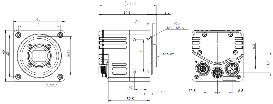
| BVS CA-GT1 C-mount | |
| Size of body (w x h x l) | 65 x 65 x 64.6 mm |

| BVS CA-GT1 C-mount with fan | |
| Size of body (w x h x l) | 65 x 65 x 75 mm |
Connectors
M12 A-coded Digital I/O and Power
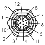
| Pin. | Signal | ImpactControlCenter numbering | Description | |
| 1 | PWR_IN | Power-In | ||
| 2 | GND (for PWR_IN) | |||
| 3 | DigOut 3 | line3 | high side solid state relays | |
| 4 | Opto DigIn 0 | line4 | opto-coupler | |
| 5 | DigOut 2 | line2 | high side solid state relays | grey |
| 6 | DigOut 0 | line0 | high side solid state relays | |
| 7 | In GND | Ground for opto-coupler (In) | ||
| 8 | Opto DigIn 2 | line6 | opto-coupler | |
| 9 | Opto DigIn 3 | line7 | opto-coupler | |
| 10 | DigOut_PWR_IN | Power-In for the high side outputs, ground via pin 2 GND | ||
| 11 | Opto DigIn 1 | line5 | opto-coupler | |
| 12 | DigOut 1 | line1 | high side solid state relays |
Camera connector (male): PHOENIX - SACC-CIP-M12MS-12P SMD R32 - 1412001 or equivalent
Matching cable and connector (female):
- Binder 79-3490-32-12 | M12 | A-coded series 763, length 2 m open end
- Binder 79-3490-35-12 | M12 | A-coded series 763, length 5 m open end
- Note
- All inputs (DigIn 1 .. DigIn 4 and GND Opto-coupler) are galvanically isolated from the camera electronics.
The level of the digital inputs can be changed between TTL and mvPLC via the registry "LineFormat".
Characteristics of the digital inputs
| Characteristics | min. | nom. | max. | Unit |
| Power-In camera power supply | 16 | 24 | 28 | V |
| Opto DigIn TTL (optional) | ||||
| Characteristics | min. | nom. | max. | Unit |
| UOpto DigIn_LOW / VIL (low level input voltage) | 0 | 1 | V | |
| UOpto DigIn_HIGH / VIH (high level input voltage) | 2.5 | 28 | V | |
| IOpto DigIn_HIGH / IIH (high level input current TTL with 5V) | 5 | mA | ||
| Opto DigIn PLC (default) | ||||
| Characteristics | min. | nom. | max. | Unit |
| UOpto DigIn_LOW / VIL (low level input voltage) | 0 | 8 | V | |
| UOpto DigIn_HIGH / VIH (high level input voltage) | 11 | 28 | V | |
| IOpto DigIn_HIGH / IIH (high level input current PLC with 24V) | 8 | mA | ||
| Opto DigIn PLC / TTL Speed | ||||
| Characteristics | min. | nom. | max. | Unit |
| Switching frequency | 5 | MHz | ||
Characteristics of the digital outputs
| Characteristics | min. | nom. | max. | Unit |
| VCC_HSD supply for the high side outputs | 10.5 | 28 | V | |
| UDIG_OUT_HIGH / Digital output, IOUT = 0.5 A | VCC_HSD - 1 | VCC_HSD - 1.4 | V | |
| IOH / High-level output current (short circuit) | 0.7 | mA | ||
| tON Turn-On time | 20 | us | ||
| tR Rise time | 8 | us | ||
| tOFF Turn-Off time | 30 | us |
Furthermore, the digital outputs feature:
- Current limitation
- Short circuit protection
- Note
- Each output has a short circuit protection between 1 A and 1.7 A (generally 1.3 A). So if you combine two outputs with one load, the short circuit protection can have an effect.
M8 A-coded Multipurpose I/O
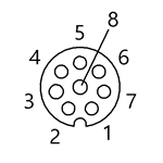
| Pin. | Signal | ImpactControlCenter numbering | Description | Pin color cable / KS-M8-8 xx.x |
| 1 | Bidirectional digital I/O 0 | line8 | I/O 0 | white |
| 2 | Bidirectional digital I/O 1 | line9 | I/O 1 | brown |
| 3 | RS232_RxD | Serial interface RS232_RX | green | |
| 4 | RS232_TxD | Serial interface RS232_TX | yellow | |
| 5 | Bidirectional digital I/O 2 | line10 | I/O 2 | grey |
| 6 | Bidirectional digital I/O 3 | line11 | I/O 3 | pink |
| 7 | GND | Ground | blue | |
| 8 | POWER_OUT | Output 12V / 500mA | red |
Camera connector (male): PHOENIX - SACC-CIP-M8FS-8P SMD R32 - 1412254 or equivalent
Matching cable and connector (female):
- Binder 79-3805-52-08 | M8 | A-coded series 718, length 2 m open end
- Binder 79-3805-55-08 | M8 | A-coded series 763, length 5 m open end
Characteristics of the digital inputs and outputs
| POWER_OUT @ Power12V | ||||
| Characteristics | min. | nom. | max. | Unit |
| UOUT (Power Voltage) | 12 | V | ||
| IOUT_max1 (short-circuit current limited) | 0.5 | A | ||
| UOUT (high level voltage I(OUT) = 500 mA) | 11 | V | ||
| Multipurpose total current limit1 Total current is the sum of currents at all high-level outputs and Power12V Power_OUT | 0.5 | A | ||
| Multipurpose IO - Output | ||||
| Characteristics | min. | nom. | max. | Unit |
| UOUT_HIGH (high-level voltage) | 10.4 (I(OUT) = 100mA) 9.8 (I(OUT) = 200mA) | 12 | V | |
| UOUT_LOW (low-level voltage) | 1.6 (I(OUT) = -100mA) 2.2 (I(OUT) = -200mA) | V | ||
| IOUT_max1 (short-circuit current limited) | 0.2 | A | ||
| td(on/off) (propagation delay) | 2.1 | 6.5 | us | |
| Switching frequency | 100 | kHz | ||
| Multipurpose IO - Input | ||||
| Characteristics | min. | nom. | max. | Unit |
| UIN_max (maximum input voltage) | 12 | 24 | V | |
| UIN_TH_HIGH (input threshold high) | 9.1 | V | ||
| UIN_TH_LOW (input threshold low) | 0 | 5.1 | V | |
| Propagation delay | 1 | 5 | us | |
1 MPP (Multipurpose) current limitation note: total current is the sum of currents at all high-level outputs and Power12V Power_OUT
M12 X-coded 1/2.5/5/10 GBit Ethernet
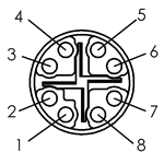
| Pin. | Signal |
| 1 | BI_DA+ |
| 2 | BI_DA- |
| 3 | BI_DB+ |
| 4 | BI_DB- |
| 5 | BI_DD+ |
| 6 | BI_DD- |
| 7 | BI_DC- |
| 8 | BI_DC+ |
- Note
- The Ethernet signals are galvanically isolated from the camera electronics.
Signal LEDs
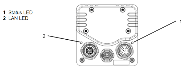
Status LED
| Status | LED color |
| Initializing | White on |
| Waiting for Ethernet link | White blink |
| LLA (auto IP) | Green blink |
| LLA got | Green on |
| Waiting for client | Blue on |
| DHCP request | Blue blink |
| DHCP got | Bright blue on |
| Fixed IP | Bright green on |
| Streaming | Green on |
| Error | Red on |
| Connected - Streaming off | Yellow on |
| Busy (e.g. firmware update) | Yellow blink |
| Excessive temperature - Camera must cool down | Fast red blink (50 ms) |
| Rescue mode | Short red blink (1 s) indicades that the camera operates in the rescue mode in combination with one of the listed states (explanation above):
|
| Under voltage | Slow red blink (2 s) |
LAN LED
This LED shows link and activity of the network interface. I.e.
- A luminous LED indicates an established link.
- The color indicates the link speed.
- A flashing LED indicates activity.
| Speed | LED color |
| 10 G | Green |
| 5 G | Blue |
| 2.5 G | White |
| <=1 G | Yellow |
| No link | Off |
Undervoltage detection
The BVS CA-GT1 family offers a circuit which detects undervoltages. If the power supply voltage becomes insufficient to operate the camera steadily, the camera will change to the undervoltage mode. That means:
- The camera cannot be reached via Ethernet anymore.
- The camera's outputs are switched off.
- The State LED shows the state "Undervoltage".
- The Network LED shows the state "No link".
- The fan (if connected) is turned off.
- The camera will be in this state until the supply voltage is sufficient again or the power source is disconnected and reconnected.
Summary of components
Summary of advanced features
The following table shows an excerpt of the advanced features. For the complete list, please use the "Product Comparison" in Appendix B. Product Comparison .
| Advanced features | BVS CA-GT1 | |
| MultiFrame / SingleFrame / Continuous | √ | |
| Trigger Overlap | √ | |
| Temperature settings | Temperature monitoring with user defined limits | √ |
| User Sets | 4 config sets storable | √ |
| User Data | 512 byte of EEPROM data | √ |
| Clock Synchronisation | IEEE1588 Master / Slave | √ |
| Timestamp (latch/reset) | Nanosecond precise camera individual 64 bit counter | √ |
| Enhanced I/O func. (counter, timer) | Timers can be used for pulse width modulation | 4 counters, 2 timers |
| Auto Exposure Control (AEC) | √ | |
| Auto Gain Control (AGC) | √ | |
| White balance | √ | |
| Auto white balance | √ | |
| RGB-to-YUV conversion | √ | |
| Color correction matrix | √ | |
| Image recorder with pretrigger option | √ | |
| Chunk Data | √ | |
| Introducing multicasting | √ | |
| Primary application switchover | √ | |
| Temperature and Fan Behavior | √ | |