Loading...
Searching...
No Matches
Sensor Overview
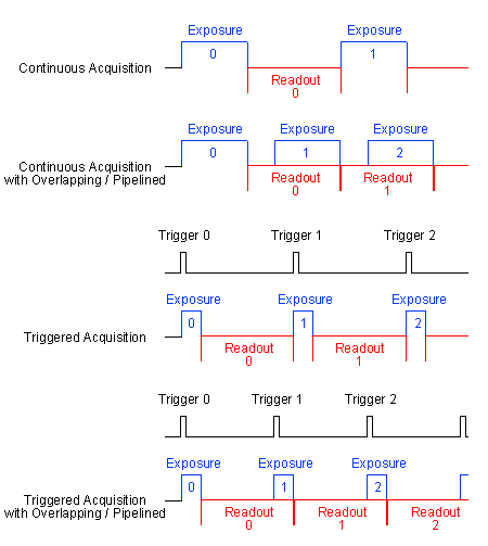
By default, the steps exposure and readout out of an image sensor are done one after the other. The pipelined CMOS sensors only support the overlapped mode. Even less CMOS sensors support the overlapped mode combined with trigger. Please check the sensor summary. In overlapping mode, the exposure starts the exposure time earlier during readout.
CMOS sensors
The CMOS sensor modules incorporate the following features:
Sony Pregius
| Sensors: | 1.6 Mpixels resolution CMOS sensor (-0016A) |
| Sensor supplier | Sony |
| Sensor name | IMX296 |
| Resolution | 1448 x 1088 gray scale or RGB Bayer mosaic |
| Indication of sensor category to be used | 1/2.9" |
| Pixel clock | 74.25 MHz |
| Max. frames per second (in free-running full frame mode) | 21.8 |
| Binning | H+V, AverageH+V (frame rate unchanged) |
| Exposure time | 10 us - 1 s |
| ADC resolution | 10 bit (10 / 8 bit transmission) |
| SNR | 41.7 dB |
| DR (normal / HDR) | 71.62 dB |
| Progressive scan sensor (no interlaced problems!) | √ |
| Rolling shutter | x |
| Global shutter | √ |
| Trigger (Hardware / Software) | √ / √ |
| Pipelined in continuous / triggered mode | √/x |
| High color reproductivity (for color version) | √ |
| Programmable readout timing with free capture windows and partial scan | √ |
| Flash control output, synchronous to exposure period | √ |
| More specific data |
Sony Starvis
| Sensors: | 5.1 Mpixels resolution CMOS sensor (-0051H) |
| Sensor supplier | Sony |
| Sensor name | IMX335 |
| Resolution | 2592 x 1944 gray scale or RGB Bayer mosaic |
| Indication of sensor category to be used | 1/2.8" |
| Pixel clock | 74.25 MHz |
| Max. frames per second (in free-running full frame mode) | 7.24 |
| Binning | H+V, AverageH+V (frame rate unchanged) |
| Exposure time | 10 us - 0.3 s |
| ADC resolution | 10 bit (10 / 8 bit transmission) |
| SNR | TBD dB |
| DR (normal / HDR) | TBD dB |
| Progressive scan sensor (no interlaced problems!) | √ |
| Rolling shutter | √ |
| Global shutter | x |
| Trigger (Hardware / Software) | √/x |
| Pipelined in continuous / triggered mode | √/x |
| High color reproductivity (for color version) | √ |
| Programmable readout timing with free capture windows and partial scan | √ |
| Flash control output, synchronous to exposure period | √ |
| More specific data |
- Note
- For further information about image errors of image sensors, please have a look at
- For further information about image errors of image sensors, please have a look at Correcting image errors of a sensor.
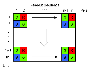
Output sequence of color sensors (RGB Bayer)
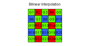
Bilinear interpolation of color sensors (RGB Bayer)
For Bayer demosaicing in the camera, we use bilinear interpolation:
-
Interpolation of green pixels: the average of the upper, lower, left and right pixel values is assigned as the G value of the interpolated pixel.
For example:(G3+G7+G9+G13) G8 = -------------- 4
For G7:(G1+G3+G11+G13) G7_new = 0.5 * G7 + 0.5 * --------------- 4 -
Interpolation of red/blue pixels:
Interpolation of a red/blue pixel at a green position: the average of two adjacent pixel values in corresponding color is assigned to the interpolated pixel.
For example:(B6+B8) (R2+R12) B7 = ------- ; R7 = -------- 2 2
Interpolation of a red/blue pixel at a blue/red position: the average of four adjacent diagonal pixel values is assigned to the interpolated pixel.
For example:(R2+R4+R12+R14) (B6+B8+B16+B18) R8 = --------------- ; B12 = --------------- 4 4
Any colored edge which might appear is due to Bayer false color artifacts.
- Note
- There are more advanced and adaptive methods (like edge sensitive ones) available if the host is doing this debayering.