Introduction
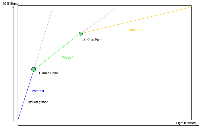
The HDR (High Dynamic Range) mode available for cameras built with the onsemi MT9V034 chip increases the usable contrast range. This is achieved by dividing the integration time in two or three phases. The exposure time proportion of the three phases can be set independently. Furthermore, it can be set, how much signal of each phase is charged.
Functionality

Description
- "Phase 0"
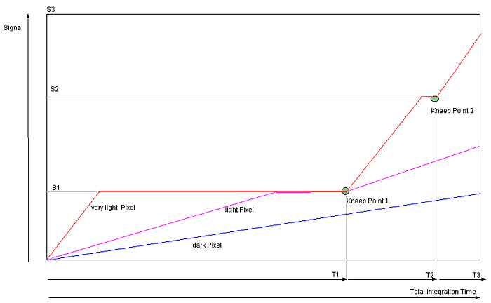
- During T1 all pixels are integrated until they reach the defined signal level of Knee Point 1.
- If one pixel reaches the level, the integration will be stopped.
- During T1 no pixel can reached a level higher than P1.
- "Phase 1"
- During T2 all pixels are integrated until they reach the defined signal level of Knee Point 2.
- T2 is always smaller than T1 so that the percentage compared to the total exposure time is lower.
- Thus, the signal increase during T2 is lower as during T1.
- The max. signal level of Knee Point 2 is higher than of Knee Point 1.
- "Phase 2"
- During T2 all pixels are integrated until the possible saturation.
- T3 is always smaller than T2, so that the percentage compared to the total exposure time is again lower here.
- Thus, the signal increase during T3 is lower as during T2.
For this reason, darker pixels can be integrated during the complete integration time and the sensor reaches its full sensitivity. Pixels, which are limited at each Knee Points, lose a part of their integration time - even more, if they are brighter.

In the diagram you can see the signal line of three different bright pixels. The slope depends of the light intensity , thus it is per pixel the same here (granted that the light intensity is temporally constant). Given that the very light pixel is limited soon at the signal levels S1 and S2, the whole integration time is lower compared to the dark pixel. In practice, the parts of the integration time are very different. T1, for example, is 95% of Ttotal, T2 only 4% and T3 only 1%. Thus, a high decrease of the very light pixels can be achieved. However, if you want to divide the integration thresholds into three parts that is S2 = 2 x S1 and S3 = 3 x S1, a hundredfold brightness of one pixel's step from S2 to S3, compared to the step from 0 and S1 is needed.
Using HDR
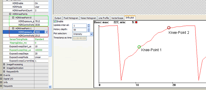
Figure 3 is showing the usage of the HDR mode. Here, an image sequence was created with the integration time between 10us and 100ms. You can see three slopes of the HDR mode. The "waves" result from the rounding during the three exposure phases. They can only be partly adjusted during one line period of the sensor.

Notes about the usage of the HDR mode
- In the HDR mode, the basic amplification is reduced by approx. 0.7, to utilize a huge, dynamic area of the sensor.
- If the manual gain is raised, this effect will be reversed.
- Exposure times, which are too low, make no sense. During the third phase, if the exposure time reaches a possible minimum (one line period), a sensible lower limit is reached.
Possible settings
Possible settings of HDR mode are:
"HDREnable":
- "Off": Standard mode
- "On": HDR mode on, reduced amplification:
- "HDRMode":
- "Fixed": Fixed setting with 2 Knee Points. modulation Phase 0 .. 33% / 1 .. 66% / 2 .. 100%
- "Fixed0": Phase 1 exposure 12.5% , Phase 2 31.25% of total exposure
- "Fixed1": Phase 1 exposure 6.25% , Phase 2 1.56% of total exposure
- "Fixed2": Phase 1 exposure 3.12% , Phase 2 0.78% of total exposure
- "Fixed3": Phase 1 exposure 1.56% , Phase 2 0.39% of total exposure
- "Fixed4": Phase 1 exposure 0.78% , Phase 2 0.195% of total exposure
- "Fixed5": Phase 1 exposure 0.39% , Phase 2 0.049% of total exposure
- "User": Variable setting of the Knee Point (1..2), threshold and exposure time proportion
- "HDRKneePointCount": Number of Knee Points (1..2)
- "HDRKneePoints"
- "HDRKneePoint-0"
- "HDRExposure_ppm": Proportion of Phase 0 compared to total exposure in parts per million (ppm)
- "HDRControlVoltage_mV": Control voltage for exposure threshold of first Knee Point (3030mV is equivalent to approx. 33%)
- "HDRKneePoint-1"
- "HDRExposure_ppm": Proportion of Phase 1 compared to total exposure in parts per million (ppm)
- "HDRControlVoltage_mV": Control voltage for exposure threshold of first Knee Point (2630mV is equivalent to approx. 66%)
- "HDRKneePoint-0"
