- Note
- The screenshots below are examples only and show how a dialog for a feature described here might look like. Not every NIC/NIC driver will support every feature discussed here and different drivers might use different names for the features presented. The hints are just meant to give an idea for what to look for.
Network Interface Card
Using the correct network interface card is crucial. In case of BVS CA-GX0 / BVS CA-GX2 this would be a 1 Gigabit Ethernet controller which is capable of full duplex transmission. In case an application shall use both links of an BVS CA-GX2 then at least a dual-port 1 Gigabit NIC is needed.
In the properties of the network interface card settings, please check, if the network interface card is operating as a "1000MBit Full Duplex Controller" and if this mode is activated.
Network Interface Card Driver
Also the network interface card manufacturers provide driver updates for their cards every now and then. Using the latest NIC drivers is always recommended and might improve the overall performance of the system dramatically!
GigE Vision™ Capture Driver
Please check, if the GigE Vision™ capture filter driver has been installed correctly by GigEConfigure.
Network Protocol Drivers
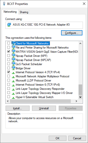
All unused protocol drivers should be disabled in order to improve the overall performance and stability of the system! In the following screen-shot the minimum set of recommended protocol drivers is enabled only. If others are needed they can be switched on but it's best to reduce the enabled drivers to a bare minimum.
- Note
- Especially filter drivers written against an older version of the NDIS specification should be disabled or even removed from the system since a single NDIS 5 (or smaller) driver in the driver stack can degrade the overall performance significantly. This is especially true for older versions of Wireshark coming with an old version of WinPcap! These should be upgraded to newer Wireshark releases using Npcap if possible and WinPcap drivers should be removed from the system! Using Wireshark at 10G is only recommended for debugging purposes. Shipped systems should NOT use Wireshark in the background since this comes with a huge performance overhead.
Maximum transmission unit (MTU) / Jumbo Frames
The camera sets the MTU to the maximum value automatically given by the NIC or switch and supports a maximum MTU of 8K. You can manually change the network packet size the camera uses for transmitting data using this property: "Setting → Base → Camera → GenICam → Transport Layer Control → Gev Stream Channel Selector → Gev SCPS Packet Size":
As a general rule of thumb it can be said, that the higher the MTU, the better the overall performance, as less network packets are needed to transmit a full image, which results in less overhead that arises from the handling of each arriving network packet in the device driver etc. However every component involved in the data transmission (that includes every switch, router and other network component, that is installed in between the device and the system receiving the packets) must support the MTU or packet size, as otherwise the first component not supporting the packet size will silently discard all packets, that are larger than the component can handle. Thus the weakest link here determines to overall performance of the full system!
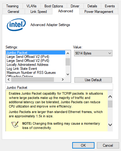
On the network interface card's side, this might look like this:
- Note
- There is no need to set the transfer packet size manually. By default Impact Acquire will determine the maximum possible packet size for the current network settings automatically when the device is initialised. However again the weakest link determines this packet size thus NICs should be chosen and configured appropriately and the same goes for switches!
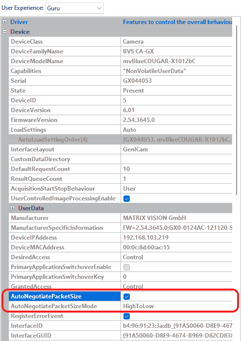
The behavior of the auto negotiation algorithm can be configured manually or to disable it completely if needed. The AutoNegotiatePacketSize property determines if Impact Acquire should try to find optimal settings at all and the way this is done can be influenced by the value of the AutoNegotiatePacketSizeMode property. The following modes for the are available:
- Note
- All components belonging to the network path (device, network interface card, switches, ...) will affect the MTU negotiation as every device will support the negotiated value.
| Value | Description |
| HighToLow | The MTU is automatically negotiated starting from the NICs current MTU down to a value supported |
| LowToHigh | The negotiation starts with a small value and then tries larger values with each iteration until the optimal value has been found |
To disable the MTU auto negotiation just set the AutoNegotiatePacketSize property to "No".
- Note
- Manually setting up the packet size should only be done if
- auto-negotiation doesn't work properly
- there are very good (e.g. application-specific) reasons for doing so
Interrupt Moderation
In the properties of the network interface card settings, please check, if the "Interrupt Moderation" is activated.
An Interrupt causes the CPU to - well - interrupt what it is currently doing. This of course consumes time and other resources so usually a system should process interrupts as little as possible. In cases of high data rates the number of interrupts might affect the overall performance of the system. The "Interrupt Moderation"-setting allows to combine interrupts of multiple packets to just a single interrupt. The downside is that this might slightly increase the latency of an individual network packet but that should usually be negligible.
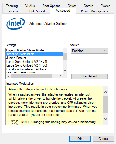
Once "Interrupt moderation" is enabled there even might be the possibility to configure the interrupt moderation rate of the network interface.
Usually there are multiple possible options which will reflect a different trade-off between latency and CPU usage. Depending on the expected data rate different values might be suitable here. Usually the NIC knows best so setting the value to Adaptive is mostly the best option. Other values should be used after careful consideration.
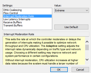
In case of high frame rates the best option sometimes might be "Extreme" when individual network packets are not needed to be processed right away. In that case however one needs to be aware of the consequences: If an application receives an incomplete image every now and then, then "Extreme" might not be the right choice since it basically means "wait until the last moment before the NIC receive buffer overflows, then generate an interrupt". While this is good in terms of minimal CPU load this of course is bad if this interrupt then is not served at once because of other interrupts as then packet data will be lost. It really depends on the whole system and sometimes needs some trial and error work. The amount of buffer reserved for receiving network data is configured by the Receive/Transmit Descriptors and combined with the Maximum transmission unit (MTU) / Jumbo Frames parameter these 3 values are the most important ones to consider!
RSS (Receive Side Scaling) Queues
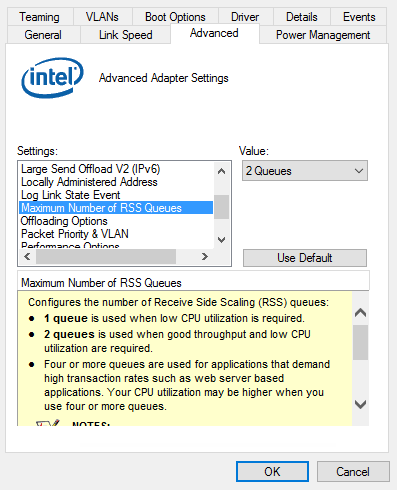
Some NICs might also offer to configure the number of "RSS (Receive Side Scaling) Queues". In certain cases this technology might help to improve the performance of the system but in some cases it might even reduce the performance.
The feature in general offers the possibility to distribute the CPU load caused by network traffic to different CPU cores instead of handling the full load just on one CPU core.
Where To Use It
- When working with cameras supporting the Balluff Multi-Core Acquisition Optimizer technology.
- In systems which work with multiple GigE-Vision cameras over one link. This would be the case if multiple Gigabit Ethernet cameras are connected to a switch which is connected to the host via e.g. a 10 Gigabit Ethernet up link port.
- If a device offers more than one network stream.
Where Not To Use It
- If multiple GigE-Vision cameras are connected via multiple NICs directly to the host.
- If a network device does just offer one network stream.
What It Does
Usually a single network stream (source and destination port and IP address) will always be processed on a single CPU in order to benefit from cache lines etc.. Switching on RSS will not change this but will try to distribute which network stream is processed on which CPU more evenly and combined NIC properties like the base CPU etc. it is even possible to configure which NIC shall use which CPU(s) in the host system.
- Note
- Configuring more RSS queues than physical cores available in the system might have even a negative impact on the overall performance! However the operating system usually knows what to do, so if your system has 6 physical CPUs and your NIC allows either 4 or 8 RSS queues then 8 is the option to use to get access to all CPU cores. Only if any kind of strange behaviour is encountered then either go with 4 queues or get in touch with our support team.
Receive/Transmit Descriptors
Please check, if the number of "Receive Descriptors" (RxDesc) and "Transmit Descriptors" (TxDesc) of the NIC is set to the maximum value!
"Receive Descriptors" are data segments either describing a segment of memory on the NIC itself or in the host systems RAM for incoming network packets. Each incoming packet needs either one or more of these descriptors in order to transfer the packets data into the host systems memory. Once the number of free receive descriptors is insufficient packets will be dropped thus leads to data losses. So for demanding applications usually the bigger this value is configured the better the overall stability.
"Transmit Descriptors" are data segments either describing a segment of memory on the NIC itself or in the host systems RAM for outgoing network packets. Each outgoing packet needs either one or more of these descriptors in order to transfer the packets data out into the network. Once the number of free transmit descriptors is insufficient packets will be dropped thus leads to data losses. So for demanding applications usually the bigger this value is configured the better the overall stability.
These values have a close relationship to the Maximum transmission unit (MTU) / Jumbo Frames as well. You can get a feeling about values with following formula:
- Note
- The formula is per camera and per network port.
network packets needed >= 1.1 * PixelPerImg * BytesPerPixel
          ---------------------------------
                       MTU
"Example 1: 1500 at 1.3MPixel"
network packets needed >= 1.1 * 1.3M * 1
          --------------
              1500
       >= 950
"Example 2: 8k at 1.3MPixel"
network packets needed >= 1.1 * 1.3M * 1
          --------------
              8192
       >= 175
Both examples are showing the required network packets per image which are NOT to be confused with the number of available receive descriptors! A descriptor (receive or transmit) usually describes a fixed size piece of memory (e.g. 2048 bytes). Now with increasing values of images per second the number of "Receive Descriptors" might be consumed very soon given that the NIC is not always served directly by the operating system. Usually, the default values reserved by the NIC driver vary between 64 and 256 and usually for acquiring uncompressed image data at average speed this is not enough. Also processing a network packet consumes some time which is independent of the size (e.g. generating an interrupt, calling upper software layers, etc.), which is why larger packets usually result in a better overall performance.
- Note
- If you are forced to use a small MTU values and/or if the NIC only supports a small value for "Receive Descriptors" or "Transmit Descriptors", the transmission might not work reliable and you might need to consider using a different NIC. You may also consider to enable Interrupt Moderation allowing the NIC to signal multiple network packets using a single interrupt to reduce the overall amount of interrupts. The downside of this of course is that some time sensitive network packets (e.g. a GigE Vision™ event sometimes might arrive in the application a little later. Usually this is acceptable but sometimes it may be not.
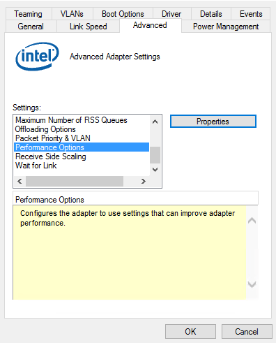
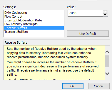
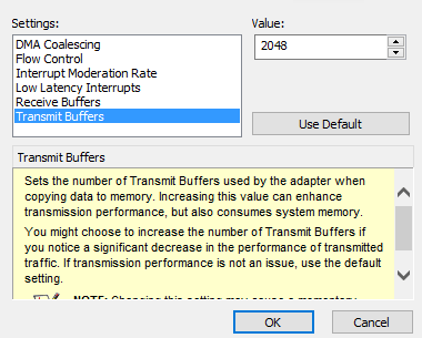
The "Receive Descriptors" a.k.a. "Receive Buffers" and "Transmit Descriptors" a.k.a. "Transmit Buffers" (Intel Ethernet Server Adapter I350-T2 network interface) can usually be found under "Performance Options":
- Note
- Depending on the used network card and device driver these options might have slightly different locations and/or names.
Link Aggregation, Teaming Or Bonding (GigE Vision™ Devices With Multiple NICs (BVS CA-GX2))
While it is possible to operate BVS CA-GX2 Dual-GigE devices with a single network cable (which requires to use the connector LAN 1 only), the usage of two network cables operated in static LAG (Link Aggregation) is recommended when the devices should run at full speed. This Link Aggregation or SLA Static Link Aggregation feature is a technology invented to increase the performance between two network devices by combining two single network interfaces to one virtual link which provides the bandwidth of both single links (e.g. two 1 GBit links would result in a virtual single 2 GBit link). Swichting the modes (single or double link) requires a reboot of the camera.
- Note
- Not relevant for building a LAG team but still important to know: Both links are used in a round robin scheme thus packages will leave the device in order they still might arrive in the device driver stack in a different order. The reason for this is that both NICs never generate an interrupt in an absolutely predictive way nor will they be served by the operating system always in a predictable manner. So assuming one NIC of the camera transmits all the odd packets and the other all the even ones (which is more or less how the BVS CA-GX2 will do it) it is still very likely or at least not uncommon, that a lot of either even or odd packets are received before a bunch of odd or even ones is processed. This depends on various factors and a driver should simply be able to deal with it. Interrupt moderation as well as thread scheduling done by the operating system and other things are at work here. As a result this means a packet with a lower block or packet ID might be received after one with a higher one. It would be fair to assume a data loss then but in case of LAG it is a little more complicated.
If two network cables should be used either a network interface card with two network interfaces or two identical network interface cards allowing to be teamed are needed. Using a single card is recommended. In addition to this requirement the network interface card has to support so-called Link Aggregation, teaming, or bonding. Normally, Windows® installs a standard device driver which does not support link aggregation. For this, you have to install and download a driver from the manufacturer's website. When e.g. using a "Intel Ethernet Server Adapter I350-T2" network controller this will be
- https://downloadcenter.intel.com/download/18713/Intel-Network-Adapter-Driver-for-Windows-7 (PROWinLegacy.exe for Windows® 7)
- https://downloadcenter.intel.com/download/25016/Ethernet-Intel-Network-Adapter-Driver-f-r-Windows-10 (PROWin.exe for Windows® 10).
- See also
- List of Intel network controllers supporting teaming with Windows® 10:
After installation you have to combine the two interfaces which are used by the BVS CA-GX2. For this, open the device driver settings of the network controller via the "Device Manager":
Windows® 7
- Open the tab "Teaming" and
-
create a new team.
Create an aggregation group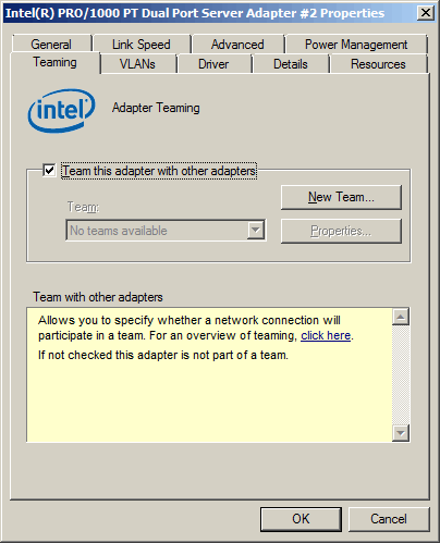
-
Then enter a name for this group e.g.
"BVS CA-GX2"and -
click on "Next".
Enter an aggregation group name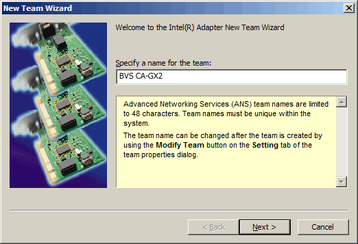
-
Select the two interfaces which where used for the BVS CA-GX2.
Select the used interfaces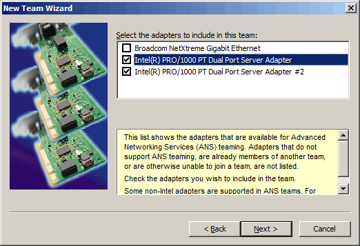
-
Finally, select the connection type "Static Link Aggregation".
Select the connection type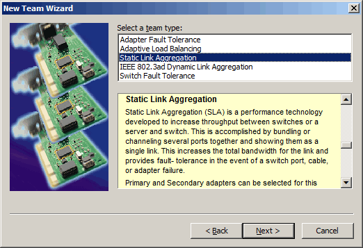
After closing the group assistant, you can connect the camera using the two network interfaces. There is no special connection necessary between camera and network controller interfaces.
It is also possible to use the camera with one network interface. This of course will result in a reduced data rate. For this use the right (primary) network interface of the camera only (the label on the back can be read normally).
Windows® 10
- Click Start (Windows® Icon in the taskbar) and type in Powershell.
- Right-click the Powershell icon and choose "Run as Administrator".
- If you are prompted to allow the action by User Account Control, click Yes .
-
Enter the command (e.g. for Intel NIC)
Import-Module -Name "C:\Program Files\Intel\Wired Networking\IntelNetCmdlets\IntelNetCmdlets"
-
Afterwards, execute the command:
New-IntelNetTeam -TeamName "MyLAGTeam" -TeamMemberNames "Intel(R) Ethernet Server Adapter I350-T2","Intel(R) Ethernet Server Adapter I350-T2 #2" -TeamMode StaticLinkAggregation
Replace MyLAGTeam with your preferred teaming name and also "Intel(R) Ethernet Server Adapter I350-T2" with the name of your used NIC.
Windows® 11
- Note
- At the moment (March 2022) there seems to be no support for Link Aggregation or SLA Static Link Aggregation using Intel network interface adapters. As Intel discontinued the support for Intel Intel® PROSet and Intel® Advanced Network Services (Intel® ANS), it is unclear if the required functionality will be availble for Windows® 11.
- See also
- More details regarding the support of Intel® network adapters can be found here:
