Loading...
Searching...
No Matches
mvBlueCOUGAR-X1010 (10 Mpix [3856 x 2764])
Introduction
The CMOS sensor module (MT9J003) incorporates the following features:
- resolution to 3856 x 2764 gray scale or RGB Bayer mosaic
- supports window AOI mode with faster readout
- programmable analog gain (0..12 dB)
- progressive scan sensor (no interlaced problems!)
- rolling shutter / global reset
- programmable readout timing with free capture windows and partial scan
- many trigger modes (free-running, hardware-triggered)
Details of operation
The sensor uses two acquisition modes:
- rolling shutter (mvShutterMode =
"ElectronicRollingShutter") and - global reset release shutter (mvShutterMode =
"GlobalResetRelease").
With the rolling shutter the lines are exposed for the same duration, but at a slightly different point in time:
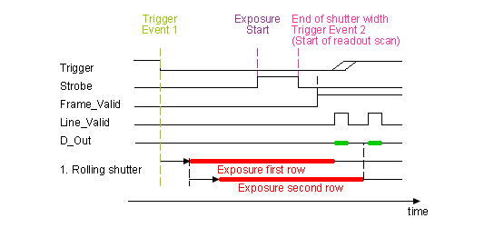
- Note
- Moving objects together with a rolling shutter can cause a shear in moving objects.
The global reset release shutter, which is only available in triggered operation, starts the exposure of all rows simultaneously and the reset to each row is released simultaneously, too. However, the readout of the lines is equal to the readout of the rolling shutter: line by line:
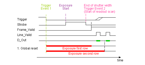
- Note
- This means, the bottom lines of the sensor will be exposed to light longer! For this reason, this mode will only make sense, if there is no extraneous light and the flash duration is shorter or equal to the exposure time.
Furthermore, the sensor offers two operating modes:
- free running mode (Overlapping exposure and readout)
- snapshot mode (Sequential exposure and readout) in triggered operation
Free running mode
In free running mode, the sensor reaches its maximum frame rate. This is done by overlapping erase, exposure and readout phase. The sensor timing in free running mode is fixed, so there is no control when to start an acquisition. This mode is used with trigger mode Continuous.
To calculate the maximum frames per second (FPSmax) in free running mode you will need following formula:
| Name | Value |
| PixelClock | 81.25 |
| VerticalBlank | 143 |
            (ImageHeight * (    1648    )) + (VerticalBlank *      1648    )
FrameTime =                 ------------                       ------------
                             PixelClock                         PixelClock
If exposure time is lower than frame time:
                1000000
FPS_max =   ----------------
               FrameTime
If exposure time is greater than frame time:
                1000000
FPS_max =   ----------------
              ExposureTime
Snapshot mode
In snapshot mode, the image acquisition process consists off several sequential phases:
Trigger
Snapshot mode starts with a trigger. This can be either a hardware or a software signal.
The following trigger modes are available:
| Setting ("GenICam") | Mode / Setting ("Device Specific") | Description |
"TriggerSelector = FrameStart" "TriggerMode = Off" | Continuous | Free running, no external trigger signal needed. |
"TriggerSelector = FrameStart" "TriggerMode = On" "TriggerSource = Software" "ExposureMode = Timed" To trigger one frame execute the TriggerSoftware@i command then. | OnDemand | Image acquisition triggered by command (software trigger). |
"TriggerSelector = AcquisitionActive" "TriggerMode = On" "TriggerSource = <desired Line>" "TriggerActivation = LevelLow" "ExposureMode = Timed" | OnLowLevel | Start an exposure of a frame as long as the trigger input is below the trigger threshold. (No FrameTrigger!) |
"TriggerSelector = AcquisitionActive" "TriggerMode = On" "TriggerSource = <desired Line>" "TriggerActivation = LevelHigh" "ExposureMode = Timed" | OnHighLevel | Start an exposure of a frame as long as the trigger input is above the trigger threshold. (No FrameTrigger!) |
"TriggerSelector = FrameStart" "TriggerMode = On" "TriggerSource = <desired Line>" "TriggerActivation = FallingEdge" "ExposureMode = Timed" | OnFallingEdge | Each falling edge of trigger signal acquires one image. |
"TriggerSelector = FrameStart" "TriggerMode = On" "TriggerSource = <desired Line>" "TriggerActivation = RisingEdge" "ExposureMode = Timed" | OnRisingEdge | Each rising edge of trigger signal acquires one image. |
"TriggerSelector = FrameStart" "TriggerMode = On" "TriggerSource = <desired Line>" "TriggerActivation = AnyEdge" "ExposureMode = Timed" | OnAnyEdge | Start the exposure of a frame when the trigger input level changes from high to low or from low to high. |
Line Mapping (TriggerSource Impact Acquire → Trigger Source GenICam™ (valid values for <desired Line>)):
| TriggerSource Impact Acquire | TriggerSource GenICam(BCX) |
| GP-IN0 | Line4 |
| GP-IN1 | Line5 |
Erase, exposure and readout
All pixels are light sensitive at the same period of time. The whole pixel core is reset simultaneously and after the exposure time all pixel values are sampled together on the storage node inside each pixel. The pixel core is read out line-by-line after exposure.
- Note
- Exposure and read out cycle is carry-out in serial; that causes that no exposure is possible during read out.
The step width for the exposure time is 1 us.
Image data is then shifted out line-by-line and transferred to memory.
To calculate the maximum frames per second (FPSmax) in snapshot mode you will need following formula:
            (ImageHeight * (    3980    )) + (VerticalBlank *      3980    )
FrameTime =                 ------------                       ------------
                             PixelClock                         PixelClock
                   1
FPS_max =   ----------------
               FrameTime
- Note
- The maximum duration of the signal ExposureActive used in Counter, Timer, or as digital output signal is limited to 172ms (96.8 MHz pixel clock) or 207ms (80 MHz pixel clock). These limits also apply to the chunk data parameter ChunkExposureTime. It does not matter which exposure time is set, the value of this parameter will always be below or equal to 172ms (96.8 MHz pixel clock) or 207ms (80 MHz pixel clock). ExposureEndEvents are generated with the help of this signal, too and for this reason they have too small timestamps above this limit.
Use Cases
As mentioned before, "Global reset release" will only make sense, if a flash is used which is brighter than the ambient light. The settings in ImpactControlCenter will look like this:
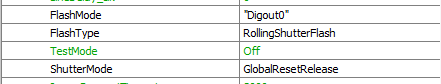
In this case, DigOut0 gets a high signal as long as the exposure time (which is synchronized with the GlobalResetRelease). This signal can start a flash light.
Frame rate calculator
- Note
- The calculator returns the max. frame rate supported by the sensor. Please keep in mind that it will depend on the interface and the used image format if this frame rate can be transferred.
Sensor Data
Device Structure
- CMOS image sensor
- Image size: 6.119(H)x4.589(V)mm (Type 1/2.3")
- Number of effective pixels: 3856 (H) x 2764 (V)
- Unit cell size: 1.67um (H) x 1.67um (V)
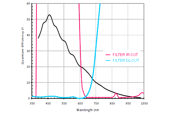
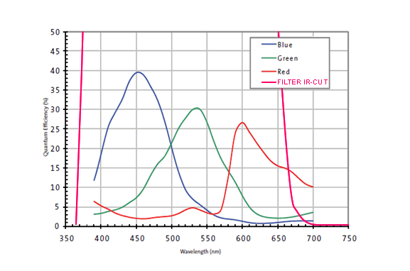
Characteristics
Color version
Gray scale version