Introduction
The Hardware Real-Time Controller (HRTC) is built into the FPGA. The user can define a sequence of operating steps to control the way how and when images are exposed and transmitted. Instead using an external PLC, the time critical acquisition control is directly build into the camera. This is a very unique and powerful feature.
Operating codes
The operating codes for each step can be one of the followings:
| OpCode | Parameter | Description |
| Nop | - | No operation |
| SetDigout | Operation array on dig out | Set a digital output |
| WaitDigin | State definition array on dig in | Wait for a digital input |
| WaitClocks | Time in us | Wait a defined time |
| Jump | HRTC program address | Jump to any step of the program |
| TriggerSet | Frame ID | Set internal trigger signal to sensor controller |
| TriggerReset | - | Reset internal trigger signal to sensor controller |
| ExposeSet | - | Set internal expose signal to sensor controller |
| ExposeReset | - | Reset internal expose signal to sensor controller |
| FrameNrReset | - | Reset internal sensor frame counter |
256 HRTC steps are possible.
The section How to use the HRTC should give the impression what everything can be done with the HRTC.
How to use the HRTC
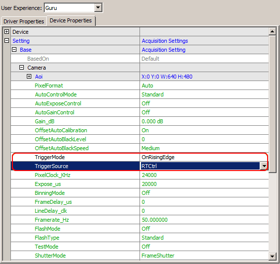
To use the HRTC you have to set the trigger mode and the trigger source. With object orientated programming languages the corresponding camera would look like this (C++ syntax):
CameraSettings->triggerMode = ctmOnRisingEdge
CameraSettings->triggerSource = ctsRTCtrl
When working with ImpactControlCenter this are the properties to modify in order to activate the evaluation of the HRTC program:

Following trigger modes can be used with HRTC:
- OnLowLevel
- OnHighLevel
- OnFallingEdge
- OnRisingEdge
- OnHighExpose
Further details about the mode are described in the API documentation:
- See also
- TCameraTriggerMode and TCameraTriggerSource in
- "Enumerations (C developers)"
- "CameraSettingsBlueFOX (C++ developers)"
- "Enumerations (C developers)"
In the Use Cases chapter there are the following HRTC sample:
- "Using single camera" :
- "Using multiple cameras" :
