Functions and data types that are available for all interface layouts. More...
Data Structures | |
| struct | ChannelData |
| A structure for image buffer channel specific data. More... | |
| struct | ImageBuffer |
| Fully describes a captured image. More... | |
| struct | RequestInfo |
| This structure contains information about the image currently associated with the request object. More... | |
| struct | RequestResult |
| Contains status information about the capture process. More... | |
| struct | TDMR_DeviceInfo |
| A structure for device specific information. More... | |
Macros | |
| #define | MVIMPACT_ACQUIRE_BUILD_VERSION 4471 |
| Returns the build version number of the current Impact Acquire release. | |
| #define | MVIMPACT_ACQUIRE_CHECK_VERSION(MAJOR, MINOR, RELEASE) |
| This is a macro which evaluates to true if the current Impact Acquire version is at least major.minor.release. | |
| #define | MVIMPACT_ACQUIRE_MAJOR_VERSION 3 |
| Returns the major version number of the current Impact Acquire release. | |
| #define | MVIMPACT_ACQUIRE_MINOR_VERSION 7 |
| Returns the minor version number of the current Impact Acquire release. | |
| #define | MVIMPACT_ACQUIRE_RELEASE_VERSION 1 |
| Returns the release version number of the current Impact Acquire release. | |
| #define | MVIMPACT_ACQUIRE_VERSION_STRING "3.7.1.4471" |
| Returns the full version number of the current Impact Acquire release as a string ("3.7.1.4471"). | |
Detailed Description
Functions and data types that are available for all interface layouts.
Data Structure Documentation
◆ ChannelData
| struct ChannelData |
A structure for image buffer channel specific data.
Channel specific data in an image is data, that in e.g. and RGB image might differ for the color components red, green and blue.
| Data Fields | ||
|---|---|---|
| int | iChannelOffset | The offset (in bytes) to the next channel. |
| int | iLinePitch | The offset (in bytes) to the next line of this channel. |
| int | iPixelPitch | The offset (in bytes) to the next pixel of this channel. |
| char | szChannelDesc[DEFAULT_STRING_SIZE_LIMIT] |
The string descriptor for this channel. For an RGB image the string values of three ChannelData structures this might e.g. be "R", "G" and "B". |
◆ ImageBuffer
| struct ImageBuffer |
Fully describes a captured image.
This class serves as a describing structure for captured images.
- Examples
- CaptureToUserMemory.c, ContinuousCapture.c, and ContinuousCaptureGenICam.c.
| Data Fields | ||
|---|---|---|
| int | iBytesPerPixel | The number of bytes per pixel. |
| int | iChannelCount |
The number of channels this image consists of. For an RGB image this value e.g. would be 3. This value defines how many ChannelData structures ImageBuffer::pChannels is pointing to once this structure has been allocated and filled with valid data. |
| int | iHeight | The height of the image in pixel or lines. |
| int | iSize |
The size (in bytes) of the whole image. This value in connection with ImageBuffer::vpData is sufficient to copy the complete image without having any additional information about it. |
| int | iWidth | The width of the image in pixel. |
| ChannelData * | pChannels | A pointer to an array of channel specific image data. |
| TImageBufferPixelFormat | pixelFormat |
The pixel format of this image. This might be important, when the image data needs to be processed or stored in a file or maybe even if the image shall be displayed. |
| void * | vpData |
The starting address of the image. This address in connection with ImageBuffer::iSize is sufficient to copy the complete image without having any additional information about it. EXAMPLE: const ImageBuffer* pib = getImageBufferFromSomewhere();
unsigned char* pTempBuf = new unsigned char[ib.iSize];
memcpy( pTempBuf, pib.vpData, pIB.iSize );
|
◆ RequestInfo
| struct RequestInfo |
This structure contains information about the image currently associated with the request object.
| Data Fields | ||
|---|---|---|
| TCameraOutput | cameraOutputUsed |
The camera output used to transmit the image to the capture device.
|
| int | exposeStart_us |
A timestamp (in us) defining the time the device started the exposure of the image associated with this request object. This value will stay 0 if nothing is known about the time the exposure did start. In such a case the timeStamp_us parameter should be used instead. |
| int | exposeTime_us |
The 'real' expose time (in us) used to generate this image. This might differ slightly from the value selected by the user via the corresponding exposure property depending on the precision available for the device or the connected camera. |
| int | frameID |
A unique frame identifier. This parameter is returned as part of the each request object. It can be used to associate a certain image with a unique identifier.
|
| int | frameNr |
The number of images captured since the driver has been initialised including the current image.
|
| double | gain_dB | The gain(in dB) this image has been taken with. |
| double | imageAverage | Currently unsupported. |
| int | lineCounter |
Line number since last trigger event. Will contain
|
| double | missingData_pc |
The amount of data missing in the current image. The value of this property will be 0 almost always. However if a device can detect blocks of missing data and an image request has returned with rrFrameIncomplete to indicate that not all the data has been captured, this property will contain the amount of data missing in percent. |
| int | timeStamp_us |
A timestamp to define the exact time this image has been captured (usually either at exposure start or exposure end, depending on the device). The timestamp is independent from the FPGA and has a resolution of 1 us.
mvBlueFOX specific: The counter of the timestamp starts when the camera gets initialized. It is measured in us. |
| int | transferDelay_us |
The time the transaction of this image has been delayed (in us) because either the bus was blocked or the CPU was busy. Normally this value will be 0. A value larger than 0 indicates that the system can't manage the current load.
|
| int | videoChannel |
The video input channel of the device this image has been acquired from.
|
◆ RequestResult
| struct RequestResult |
Contains status information about the capture process.
This part of a complete request contains general status information about the request or the image currently referenced by it.
- Examples
- CaptureToUserMemory.c, ContinuousCapture.c, and ContinuousCaptureGenICam.c.
| Data Fields | ||
|---|---|---|
| TRequestResult | result |
The result of this request. This parameter indicates whether a previous image acquisition has been successful or not. |
| TRequestState | state |
The current state of this request. This parameter indicates the current state of this request. A request e.g. can currently be idle. This would mean, that it is currently not used for image acquisition. Also a request can be in 'Capturing' state, which means it is currently processed by the driver. |
◆ TDMR_DeviceInfo
| struct TDMR_DeviceInfo |
A structure for device specific information.
- See also
- DMR_GetDeviceInfo()
Macro Definition Documentation
◆ MVIMPACT_ACQUIRE_BUILD_VERSION
| #define MVIMPACT_ACQUIRE_BUILD_VERSION 4471 |
Returns the build version number of the current Impact Acquire release.
- Returns
- The build version number of Impact Acquire
◆ MVIMPACT_ACQUIRE_CHECK_VERSION
| #define MVIMPACT_ACQUIRE_CHECK_VERSION | ( | MAJOR, | |
| MINOR, | |||
| RELEASE ) |
This is a macro which evaluates to true if the current Impact Acquire version is at least major.minor.release.
For example, to test if the program will be compiled with Impact Acquire 2.0 or higher, the following can be done:
- Since
- 2.0.0
◆ MVIMPACT_ACQUIRE_MAJOR_VERSION
| #define MVIMPACT_ACQUIRE_MAJOR_VERSION 3 |
Returns the major version number of the current Impact Acquire release.
- Returns
- The major version number of Impact Acquire
◆ MVIMPACT_ACQUIRE_MINOR_VERSION
| #define MVIMPACT_ACQUIRE_MINOR_VERSION 7 |
Returns the minor version number of the current Impact Acquire release.
- Returns
- The minor version number of Impact Acquire
◆ MVIMPACT_ACQUIRE_RELEASE_VERSION
| #define MVIMPACT_ACQUIRE_RELEASE_VERSION 1 |
Returns the release version number of the current Impact Acquire release.
- Returns
- The release version number of Impact Acquire
◆ MVIMPACT_ACQUIRE_VERSION_STRING
| #define MVIMPACT_ACQUIRE_VERSION_STRING "3.7.1.4471" |
Returns the full version number of the current Impact Acquire release as a string ("3.7.1.4471").
- Returns
- The full version string of Impact Acquire
Enumeration Type Documentation
◆ TAcquisitionMode
| enum TAcquisitionMode |
Defines valid acquisition modes.
◆ TAcquisitionStartStopBehaviour
Defines valid modes for acquisition start/stop behaviour.
- Since
- 1.12.11
◆ TAoiMode
| enum TAoiMode |
Defines valid Area Of Interest modes.
| Enumerator | ||
|---|---|---|
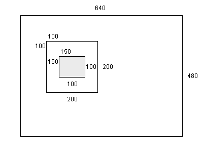
| amCentered | 0 | Use a small centered window for image processing. In this mode, a device and processing function dependent window in the middle of the AOI captured from the device will be used for the processing function.
Example:
Now in the centered AOI mode a processing function will use a window smaller than the AOI in the middle of the image. The starting point can be calculated by the formula: offsetX = ( width - ( width / 2 ) ) / 2
offsetY = ( height - ( height / 2 ) ) / 2
The used AOI is just width / 2 * height / 2 thus takes up the center quarter of the selected AOI. 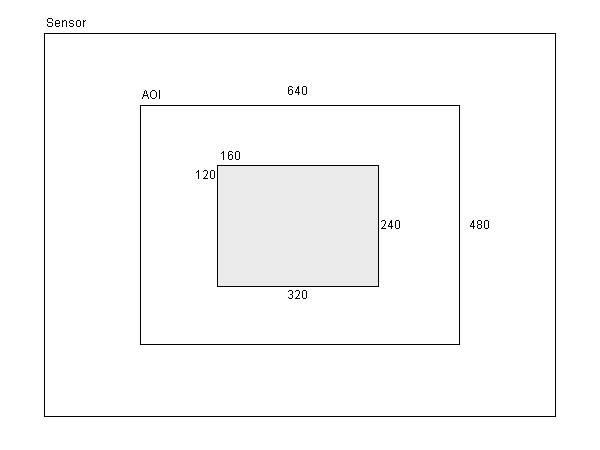
In case of an AOI defined by the user, the central AOI of the delivered image is used.
|
| amFull | Use the complete image for image processing. | |
| amUseAoi | Use a user defined AOI window for image processing. | |
◆ TBayerConversionMode
| enum TBayerConversionMode |
Defines the Bayer conversion algorithm to use.
| Enumerator | |
|---|---|
| bcmLinearInterpolation | Linear interpolation. This mode is fast but especially sharp edges will appear slightly blurred in the resulting image. |
| bcmAdaptiveEdgeSensing | Adaptive edge sensing. This mode requires more CPU time than linear interpolation, but the resulting image more closely matches the original scene. Edges will be reconstructed with higher accuracy except for noisy images. For better results in noisy images bcmLinearInterpolation is the recommended mode. |
| bcmAuto | Auto. This mode automatically sets the Bayer conversion algorithm according to the format property of the camera description. |
| bcmPacked | Packed. In this mode the resulting image will have half the height of the source image. The following algorithm will be used for generating the resulting image: 1 2 3 4 ... n
1 R G R G ... R G
2 G B G B ... G B
| 1 | 2 | 3 | 4 | 5 |...| n |
1 |RGB|RGB|RGB|RGB|RGB|...|RGB|
R1(dest) = R11
G1(dest) = (G12 + G21) / 2
B1(dest) = B22
R2(dest) = (R11 + R13) / 2
G2(dest) = ((G12 + G21) / 2) + (G12 + G23)) / 2
B2(dest) = (B22 + B24) / 2
...
Rn(dest) = R1(n-1)
Gn(dest) = (G1(n) + G2(n-1)) / 2
Bn(dest) = B2(n)
This mode is mainly useful for line scan cameras as for area cameras this would modify the aspect ratio.
|
| bcmLinearPacked | Linear Packed. In this mode the resulting image will have half the height of the source image. The following algorithm will be used for generating the resulting image: 1 2 3 4 ... n
1 R G R G ... R G
2 G B G B ... G B
| 1 | 2 | 3 | 4 | 5 |...| n |
1 |RGB|RGB|RGB|RGB|RGB|...|RGB|
2 |RGB|RGB|RGB|RGB|RGB|...|RGB|
R1(dest) = R11
G1(dest) = G21
B1(dest) = B22
R2(dest) = (R11 + R13) / 2
G2(dest) = G12
B2(dest) = B22
R3(dest) = R13
G3(dest) = G23
B3(dest) = (B22 + B24) / 2
...
Rn(dest) = R1(n-1)
Gn(dest) = G1(n)
Bn(dest) = B2(n)
This mode is mainly useful for line scan cameras as for area cameras this would modify the aspect ratio.
|
| bcmAdaptiveEdgeSensingPlus | Adaptive edge sensing plus. This mode is even more demanding CPU-wise than adaptive edge sensing, but the resulting image is sharper and has fewer artifacts. The parameters of the sharpening filter can be set by the user, to fit specific needs.
|
| bcmAdaptiveHomogeneityDirected | Adaptive edge sensing plus. This mode is most demanding CPU-wise, but the resulting image will have the best possible quality. It is based on the following algorithm: K. Hirakawa, T.W. Parks, Adaptive Homogeneity-Directed Demosaicing Algorithm, IEEE Trans. Image Processing, March, 2005.
|
◆ TBayerMosaicParity
| enum TBayerMosaicParity |
Defines valid Bayer formats.
◆ TBayerWhiteBalanceResult
Defines valid results of a white balance calibration.
◆ TBoolean
| enum TBoolean |
◆ TBufferPartDataType
| enum TBufferPartDataType |
Defines buffer part data types.
- Since
- 2.20.0
◆ TCameraDataFormat
| enum TCameraDataFormat |
Defines the data format the camera is sending (deprecated.
- Deprecated
- Beginning with the release of 3.0.0 of Impact Acquire everything specifically related to frame grabber boards will be considered as deprecated and might be removed without further notice!
| Enumerator | ||
|---|---|---|
| cdfUnknown | 0 | This is an unknown type.
|
| cdfMono | This is a mono data format.
| |
| cdfBayer | This is a Bayer format.
| |
| cdfBayerPacked | This is a Bayer Packed format. For each object line there is a red and a blue raw line to calculate the resulting color line.
| |
| cdfRGB | This is a RGB format.
| |
| cdfYUV | This is a YUV format.
| |
◆ TCameraOutput
| enum TCameraOutput |
Defines valid ways a camera can offer image data to a capture device (deprecated.
- Deprecated
- Beginning with the release of 3.0.0 of Impact Acquire everything specifically related to frame grabber boards will be considered as deprecated and might be removed without further notice!
| Enumerator | ||
|---|---|---|
| coUndefined | -1 | Specifies an undefined output.
|
| coAuto | 0 | Auto mode. Here the capture device tries to guess how the data is transmitted.
|
| coComposite | 1 | The camera will offer an analogue composite video signal.
|
| coBase | 2 | The camera will offer CameraLink® Base compliant image data.
|
| coDigital | 3 | The camera will offer digital image data.
|
| coSVideo | 4 | The camera will offer an analogue SVideo signal.
|
| coMedium | 5 | The camera will offer CameraLink® Medium compliant image data.
|
| coRGB | 6 | The camera will offer an analogue RGB signal.
|
| co2xComposite | 7 | Two cameras will offer two synchronous analogue signals.
|
| co3xComposite | 8 | Three cameras will offer three synchronous analogue signals.
|
| co4xComposite | 9 | Four cameras will offer four synchronous analogue signals.
|
| coFull | 10 | The camera will offer CameraLink® Full compliant image data.
|
| coSDSDI | 11 | The camera will offer serial digital interface(SDI) SD signal.
|
| coHDSDI | 12 | The camera will offer serial digital interface(SDI) HD signal.
|
| co3GSDI | 13 | The camera will offer serial digital interface(SDI) 3G signal.
|
◆ TChannelSplitMode
| enum TChannelSplitMode |
Defines valid modes for channel split filters.
◆ TColorProcessingMode
| enum TColorProcessingMode |
Defines the color processing mode.
◆ TColorTwistInputCorrectionMatrixMode
Defines valid values for input color correction matrices.
- Since
- 2.2.2
◆ TColorTwistOutputCorrectionMatrixMode
Defines valid values for output color correction matrices.
- Since
- 2.2.2
◆ TDarkCurrentFilterMode
Defines valid modes for the dark current filter.
| Enumerator | ||
|---|---|---|
| dcfmOff | 0 | The filter is switched off. |
| dcfmOn | The filter is switched on. | |
| dcfmCalibrateDarkCurrent | The next selected number of images will be taken for calculating the dark current correction image. In this mode after the correction image has been calculated the mode will automatically switch back to dcfmOff | |
| dcfmTransmitCorrectionImage | In this mode whenever reaching this filter, the captured image will be replaced by the last correction image, that has been created as a result of the filter being calibrated.
| |
◆ TDefectivePixelsFilterMode
Defines valid modes for defective pixels filter.
| Enumerator | ||
|---|---|---|
| dpfmOff | 0 | This filter is switched off. |
| dpfm3x1Average | The filter is active, detected defective pixels will be replaced with the average value from the left and right neighbor pixel. | |
| dpfm3x3Median | The filter is active, detected defective pixels will be replaced with the median value calculated from the nearest neighbors (3x3). | |
| dpfmResetCalibration | reset the calibration, delete all internal lists. | |
| dpfmCalibrateLeakyPixel | Detect defective leaky pixels within the next frame captured. These are pixels that produce a higher read out value than the average when the sensor is not exposed. | |
| dpfmCalibrateColdPixel | Detect defective cold pixels within the next frame captured. These are pixels that produce a lower read out code than the average when the sensor is exposed to light. | |
| dpfmCalibrateHotPixel | Detect defective hot pixels within the next frame captured. These are pixels that produce a higher read out code than the average when the sensor is exposed to light.
| |
| dpfmCalibrateHotAndColdPixel | Detect defective hot and cold pixels within the next frame captured. These are pixels that produce either a higher or a lower read out code than the average when the sensor is exposed to light. This effectively combines dpfmCalibrateColdPixel and dpfmCalibrateHotPixel
| |
| dpfmReplaceDefectivePixelAfter3x3Filter | The filter is active, detected defective pixel will be replaced and treated as being fed into a 3x3 de-Bayer algorithm before reaching the filter. This is a rather special mode that only makes sense for very specific use cases:
A far better way to tackle this of course would be (in that order):
This mode will only operate on packed RGB or packed YUV444 data! It will assume that when given a pixel p all the surrounding pixels marked with a d in the following section need to be replaced as well(- stands for other pixels NOT affected by the replacement operation): ---------------
---------------
----ddd--------
----dpd--------
----ddd--------
---------------
| |
◆ TDeviceAccessMode
| enum TDeviceAccessMode |
Defines valid device access modes.
| Enumerator | |
|---|---|
| damUnknown | Unknown device access mode. |
| damNone | No access to the device. |
| damRead | Requested or obtained read access to the device. Properties can be read but can't be changed. |
| damControl | Requested or obtained control access to the device. Properties can be read and changed, other applications might establish read access. |
| damExclusive | Requested or obtained exclusive access to the device. Properties can be read and changed, other applications can't establish access to the device. |
◆ TDeviceAutoNegotiatePacketSizeMode
Defines the way the packet size auto negotiation is handled for GigE Vision™ devices.
All modes will eventually result in the optimal packet value. However depending on the network setup one method might be faster than another.
| Enumerator | |
|---|---|
| danpsmHighToLow | Start with the maximum possible packet size. If set to danpsmHighToLow the packet size auto negotiation starts with the NICs current MTU value. If this value is too large (in terms of not all network components support it) decreasing sizes will be tried until the optimal (thus highest value supported by all network components) has been found.
|
| danpsmLowToHigh | Start with the minimal possible packet size. If set to danpsmLowToHigh the packet size auto negotiation starts with the smallest possible MTU. Afterwards increasing sizes will be tried until the optimal (thus highest value supported by all network components) has been found.
|
◆ TDeviceCapability
| enum TDeviceCapability |
Defines valid device capabilities.
Values of these enum type may be 'OR'ed together.
| Enumerator | ||
|---|---|---|
| dcNone | 0x0 | A dummy constant to indicate, that this device does not have any capabilities defined by other constants belonging to this enumeration. |
| dcHotplugable | 0x1 | This is a device that supports hot plugging. |
| dcSelectableVideoInputs | 0x2 | This is a device, that has more than one video input channel. |
| dcNonVolatileUserMemory | 0x4 | This device has non volatile memory, the user can write to and read from. |
| dcCameraDescriptionSupport | 0x8 | This device supports camera descriptions. This is a feature mainly interesting for frame grabbers. |
| dcEventSupport | 0x10 | This device supports events. |
◆ TDeviceClass
| enum TDeviceClass |
◆ TDeviceInterfaceLayout
Defines valid interface layouts for the device.
The device interface layout defines what kind of features will be available after the device driver has been opened and where these features will be located. Apart from that the interface layout also has impact at what time property values will be buffered for buffer captures.
| Enumerator | ||
|---|---|---|
| dilDeviceSpecific | 1 | A device specific interface shall be used(deprecated for all GenICam™ compliant devices). For most devices supported by this SDK this will be the only interface layout available. In this interface layout also most of the features will have the same name and location for every device even if a device is operated using another device driver. However this interface layout requires the driver to have detailed information about the underlying hardware, thus it will not be available for any third party hardware which might be usable with a certain device driver. In contrast to the other interface layouts, this layout will use a buffered property approach. This means that consecutive buffers can be requested each using defined but different settings. At the time of requesting a buffer, the driver will internally store the current property settings and will re-program the hardware later at the time of processing this request if the current settings differ from the settings that shall be used for this request.
|
| dilGenICam | 2 | A GenICam™ like interface layout shall be used. This interface layout will be available when a device is (or claims to be) compliant with a the GenICam™ standard, thus provides a GenICam™ compliant XML interface description. This also applies for third party devices, which can be used with the GenICam™ GenTL Producer of Impact Acquire. In this interface layout property value changes will always have immediate effect, thus when changing the exposure time directly after requesting a buffer this buffer might be captured with the new exposure time already depending on the time the buffer request is actually be processed.
|
◆ TDeviceLoadSettings
| enum TDeviceLoadSettings |
Defines valid modes for the loading of settings during initialization.
Whenever a Device is initialized this enumeration type defines the mode the Device tries to restore settings from a previously stored session.
| Enumerator | ||
|---|---|---|
| dlsAuto | 0 | Tries to load settings automatically following an internal procedure. The load cycle at initialization time is like this: look for a setting for this particular device (via serial number)
if not found
look for a setting for this device type (via string in property 'Product' )
if not found
look for a setting for this device family (via string in property 'Family' )
if not found
use the default settings
Under Linux® the current directory will be searched for files named <serialNumber>.xml, <productString>.xml and <familyString.xml> while under Windows® the registry will be searched for keys with these names. This only happens once (when the device is opened) |
| dlsNoLoad | No stored settings will be loaded at start-up. The device will be initialized with the drivers default values. | |
◆ TDeviceState
| enum TDeviceState |
Defines valid Device states.
| Enumerator | ||
|---|---|---|
| dsAbsent | 0 | The Device has been unplugged. The Device has present been since the DeviceManager has been initialized, but has been unplugged now and the driver has detected the unplugging of the device. Automatic detection of unplugging events is only possible for devices that support plug and play, other device drivers will only check if a device is still present if an application triggered this check. |
| dsPresent | The Device is currently connected and initialized. | |
| dsInitializing | The Device is connected and is currently initializing. | |
| dsUnreachable | This device is recognized, but can't be accessed currently. This e.g. can be the case, if this is a device connected via a network and the device does not respond to one of the recognized network protocols or if another client is already connected to this device and the device does not support multiple clients. | |
| dsPowerDown | This device is present, but currently switched into a low power consumption mode. | |
◆ TDMR_DeviceInfoType
| enum TDMR_DeviceInfoType |
Defines valid info query types, which can be passed to the function DMR_GetDeviceInfoEx().
| Enumerator | ||
|---|---|---|
| dmditDeviceInfoStructure | 0 | Used to query a small structure containing some information about the device. DMR_GetDeviceInfoEx() will expect a pointer to a TDMR_DeviceInfo structure when called with dmditDeviceInfoStructure. |
| dmditDeviceIsInUse | 1 | Checks if the device is in use by an application. The output value will be a 4 byte unsigned integer. A value different from 0 indicates the device is already in use. In this case the device might be in use either by the current process, by another process running on this machine or even by a process running on a different machine(e.g. when talking to a network device).
|
| dmdithDeviceDriver | 2 | Returns a handle providing access to device driver library specific features. The output value will be a HOBJ. This list does exist only once per device driver library. Changes in this list will affect all devices that are operated using this device driver library.
|
◆ TDMR_DeviceSearchMode
Valid search modes for the function DMR_GetDevice() when searching for a certain device.
- Note
- dmdsmUseDevID can be 'ored' (|) together with all the other modes.
| Enumerator | ||
|---|---|---|
| dmdsmSerial | 1 | Searches for a device with a certain serial number. |
| dmdsmFamily | 2 | Searches for a device belonging to a certain family. |
| dmdsmProduct | 3 | Searches for a devices with a certain product string identifier. |
| dmdsmUseDevID | 0x8000 | This flag can be 'ored' (|) together with one of the other values. When dmdsmUseDevID is specified, the device is located via the criteria specified above AND the device must have a certain ID stored into some internal memory. |
◆ TDMR_ERROR
| enum TDMR_ERROR |
Errors reported by the device manager.
These are errors which might occur in connection with the device manager itself or while working with the single devices.
| Enumerator | ||
|---|---|---|
| DMR_NO_ERROR | 0 | The function call was executed successfully. |
| DMR_DEV_NOT_FOUND | -2100 | The specified device can't be found. This error occurs either if an invalid device ID has been passed to the device manager or if the caller tried to close a device which currently isn't initialized. |
| DMR_INIT_FAILED | -2101 | The device manager couldn't be initialized. This is an internal error. |
| DMR_DRV_ALREADY_IN_USE | -2102 | The device is already in use. This error e.g. will occur if this or another process has initialized this device already and an application tries to open the device once more or if a certain resource is available only once but shall be used twice. |
| DMR_DEV_CANNOT_OPEN | -2103 | The specified device couldn't be initialized. |
| DMR_NOT_INITIALIZED | -2104 | The device manager or another module hasn't been initialized properly. This error occurs if the user tries e.g. to close the device manager without having initialized it before or if a library used internally or a module or device associated with that library has not been initialized properly or if |
| DMR_DRV_CANNOT_OPEN | -2105 | A device could not be initialized. In this case the log-file will contain detailed information about the source of the problem. |
| DMR_DEV_REQUEST_QUEUE_EMPTY | -2106 | The devices request queue is empty. This error e.g. occurs if the user waits for an image request to become available at a result queue without having send an image request to the device before. |
| DMR_DEV_REQUEST_CREATION_FAILED | -2107 | A request object couldn't be created. The creation of a request object failed. This might e.g. happen, if the system runs extremely low on memory. |
| DMR_INVALID_PARAMETER | -2108 | An invalid parameter has been passed to a function. This might e.g. happen if a function requiring a pointer to a structure has been passed an unassigned pointer or if a value has been passed, that is either too large or too small in that context. |
| DMR_EXPORTED_SYMBOL_NOT_FOUND | -2109 | One or more symbols needed in a detected driver library couldn't be resolved. In most cases this is an error handled internally. So the user will not receive this error code as a result of a call to an API function. However when the user tries to get access to an IMPACT buffer type while the needed IMPACT Base libraries are not installed on the target system this error code also might be returned to the user. |
| DEV_UNKNOWN_ERROR | -2110 | An unknown error occurred while processing a user called driver function. |
| DEV_HANDLE_INVALID | -2111 | A driver function has been called with an invalid device handle. |
| DEV_INPUT_PARAM_INVALID | -2112 | A driver function has been called but one or more of the input parameters are invalid. There are several possible reasons for this error: |
| DEV_WRONG_INPUT_PARAM_COUNT | -2113 | A function has been called with an invalid number of input parameters. |
| DEV_CREATE_SETTING_FAILED | -2114 | The creation of a setting failed. This can either happen, when a setting with the same name as the one the user tried to create already exists or if the system can't allocate memory for the new setting. |
| DEV_REQUEST_CANT_BE_UNLOCKED | -2115 | The unlock for a Request object failed. This might happen, if the Request is not locked at the time of calling the unlock function. It either has been unlocked by the user already or this request has never been locked as the request so far has not been used to capture image data into its buffer. Another reason for this error might be that the user tries to unlock a request that is currently processed by the device driver. |
| DEV_INVALID_REQUEST_NUMBER | -2116 | The number for the Request object is invalid. The max. number for a Request object is the value of the property RequestCount in the SystemSettings list - 1. |
| DEV_LOCKED_REQUEST_IN_QUEUE | -2117 | A Request that hasn't been unlocked has been passed back to the driver. This error might occur if the user requested an image from the driver but hasn't unlocked the Request that will be used for this new image. |
| DEV_NO_FREE_REQUEST_AVAILABLE | -2118 | The user requested a new image, but no free Request object is available to process this request. |
| DEV_WAIT_FOR_REQUEST_FAILED | -2119 | The wait for a request failed. This might have several reasons: |
| DEV_UNSUPPORTED_PARAMETER | -2120 | The user tried to get/set a parameter, which is not supported by this device. |
| DEV_INVALID_RTC_NUMBER | -2121 | The requested real time controller is not available for this device. |
| DMR_INTERNAL_ERROR | -2122 | Some kind of internal error occurred. More information can be found in the *.log-file or the debug output. |
| DMR_INPUT_BUFFER_TOO_SMALL | -2123 | The user allocated input buffer is too small to accommodate the result. |
| DEV_INTERNAL_ERROR | -2124 | Some kind of internal error occurred in the device driver. More information can be found in the *.log-file or the debug output. |
| DMR_LIBRARY_NOT_FOUND | -2125 | One or more needed libraries are not installed on the system. |
| DMR_FUNCTION_NOT_IMPLEMENTED | -2126 | A called function or accessed feature is not available for this device. |
| DMR_FEATURE_NOT_AVAILABLE | -2127 | The feature in question is (currently) not available for this device or driver. This might be because another feature currently blocks the one in question from being accessible. More information can be found in the *.log-file or the debug output. |
| DMR_EXECUTION_PROHIBITED | -2128 | The user is not permitted to perform the requested operation. This e.g. might happen if the user tried to delete user data without specifying the required password. |
| DMR_FILE_NOT_FOUND | -2129 | The specified file can't be found. This might e.g. happen if the current working directory doesn't contain the file specified. |
| DMR_INVALID_LICENCE | -2130 | The licence doesn't match the device it has been assigned to. When e.g. upgrading a device feature each licence file is bound to a certain device. If the device this file has been assigned to has a different serial number then the one used to create the licence this error will occur. |
| DEV_SENSOR_TYPE_ERROR | -2131 | There is no sensor found or the found sensor type is wrong or not supported. |
| DMR_CAMERA_DESCRIPTION_INVALID | -2132 | A function call was associated with a camera description, that is invalid. One possible reason might be, that the camera description has been deleted(driver closed?).
|
| DMR_NEWER_LIBRARY_REQUIRED | -2133 | A suitable driver library to work with the device manager has been detected, but it is too old to work with this version of the mvDeviceManager library. This might happen if two different drivers have been installed on the target system and one introduces a newer version of the device manager that is not compatible with the older driver installed on the system. In this case this error message will be written into the log-file together with the name of the library that is considered to be too old.
|
| DMR_TIMEOUT | -2134 | A general timeout occurred. This is the typical result of functions that wait for some condition to be met with a timeout among their parameters. More information can be found in the *.log-file or the debug output.
|
| DMR_WAIT_ABANDONED | -2135 | A wait operation has been aborted. This e.g. might occur if the user waited for some message to be returned by the driver and the device driver has been closed within another thread. In order to inform the user that this waiting operation terminated in an unusual wait, DMR_WAIT_ABANDONED will be returned then.
|
| DMR_EXECUTION_FAILED | -2136 | The execution of a method object or reading/writing to a feature failed. More information can be found in the log-file.
|
| DEV_REQUEST_ALREADY_IN_USE | -2137 | This request is currently used by the driver. This error may occur if the user tries to send a certain request object to the driver by a call to the corresponding image request function.
|
| DEV_REQUEST_BUFFER_INVALID | -2138 | A request has been configured to use a user supplied buffer, but the buffer pointer associated with the request is invalid.
|
| DEV_REQUEST_BUFFER_MISALIGNED | -2139 | A request has been configured to use a user supplied buffer, but the buffer pointer associated with the request has an incorrect alignment. Certain devices need aligned memory to perform efficiently thus when a user supplied buffer shall be used to capture data into this buffer must follow these alignment constraints
|
| DEV_ACCESS_DENIED | -2140 | The requested access to a device could not be granted. There are multiple reasons for this error code. Detailed information can be found in the *.log-file. POSSIBLE CAUSES: • an application tries to access a device exclusively that is already open in another process
|
| DMR_PRELOAD_CHECK_FAILED | -2141 | A pre-load condition for loading a device driver failed. Certain device drivers may depend on certain changes applied to the system in order to operate correctly. E.g. a device driver might need a certain environment variable to exist. When the device manager tries to load a device driver it performs some basic checks to detect problems like this. When one of these checks fails the device manager will not try to load the device driver and an error message will be written to the selected log outputs.
|
| DMR_CAMERA_DESCRIPTION_INVALID_PARAMETER | -2142 | One or more of the camera descriptions parameters are invalid for the grabber it is used with. There are multiple reasons for this error code. Detailed information can be found in the *.log-file. This error code will be returned by frame grabbers only.
|
| DMR_FILE_ACCESS_ERROR | -2143 | A general error returned whenever there has been a problem with accessing a file. There can be multiple reasons for this error and a detailed error message will be sent to the log-output whenever this error code is returned.
|
| DMR_INVALID_QUEUE_SELECTION | -2144 | An error returned when the user application attempts to operate on an invalid queue.
|
| DMR_ACQUISITION_ENGINE_BUSY | -2145 | An error returned when the user application attempts to start the acquisition engine at a time, where it is already running.
|
| DMR_BUSY | -2146 | An error returned when the user application attempts to perform any operation that currently for any reason cannot be started because something else already running. The log-output will provide additional information.
|
| DMR_OUT_OF_MEMORY | -2147 | An error returned when for any reason internal resources (memory, handles, ...) cannot be allocated. The log-output will provide additional information.
|
| DMR_LAST_VALID_ERROR_CODE | -2199 | Defines the last valid error code value for device and device manager related errors. |
- Examples
- Callback.c, CaptureToUserMemory.c, ContinuousCapture.c, and ContinuousCaptureGenICam.c.
◆ TDMR_ListType
| enum TDMR_ListType |
Defines valid interface list types, which can be located using the function DMR_FindList().
| Enumerator | ||
|---|---|---|
| dmltUndefined | -1 | A placeholder for an undefined list type. |
| dmltSetting | 0 | Specifies a certain setting. An additional string defines the name of the setting to look for. |
| dmltRequest | 1 | Specifies the list of driver owned image request objects. |
| dmltRequestCtrl | 2 | Specifies a certain image request control. An additional string defines the name of the setting to look for. |
| dmltInfo | 3 | Specifies the driver interfaces list containing general information. This e.g. can be properties containing the driver version, the current state of the device and stuff like that. |
| dmltStatistics | 4 | Specifies the driver interface list containing statistical information. This list e.g. might contain the current frame rate, the total number of images captured, etc.. |
| dmltSystemSettings | 5 | Specifies the driver interface list containing properties, which influence the overall operation of the device. This list e.g. might contain the priority of the drivers internal worker thread, the number of request objects the driver shall work with, etc.. |
| dmltIOSubSystem | 6 | Specifies the driver interface list containing properties to work with any kind of I/O pin belonging to that device. Here properties addressing the digital inputs and outputs and other I/O related properties can be found. |
| dmltRTCtr | 7 | Specifies the driver interface list providing access to the drivers Hardware Real-Time Controller (HRTC). Here properties to control the behaviour of the HRTCs can be found.
|
| dmltCameraDescriptions | 8 | Specifies the driver interface list providing access to the recognized camera description lists. Within this list all recognized camera descriptions can be found, each forming a sub list containing the properties describing the camera.
|
| dmltDeviceSpecificData | 9 | Specifies the driver interface list providing access to the device specific settings lists.
|
| dmltImageMemoryManager | 12 | Specifies the driver interface list providing access to the devices memory manager list.
This list will contain properties and lists providing access to settings related to the memory handling used by the device. E.g. the buffer size for individual DMA blocks can be configured here.
|
| dmltDeviceDriverLib | 13 | Specifies the device driver lib. An additional string defines the name of the device driver lib to look for.
|
◆ TFlatFieldFilterCorrectionMode
Defines valid modes for the flat field correction.
| Enumerator | ||
|---|---|---|
| ffcmDefault | 0 | The default flat field correction is used. |
| ffcmBrightPreserving | The flat field correction with clipping compensation is used. This mode prevents clipping artifacts when overexposing the image, but may cause missing codes in the histogram and a brighter image. | |
◆ TFlatFieldFilterMode
| enum TFlatFieldFilterMode |
Defines valid modes for the flat field filter.
| Enumerator | ||
|---|---|---|
| fffmOff | 0 | The filter is switched off. |
| fffmOn | The filter is switched on. | |
| fffmCalibrateFlatField | The next selected number of images will be taken for calculating the flat field correction image. In this mode after the correction image has been calculated the mode will automatically switch back to fffmOff | |
| fffmTransmitCorrectionImage | In this mode whenever reaching this filter, the captured image will be replaced by the last correction image, that has been created as a result of the filter being calibrated.
| |
◆ THWUpdateResult
| enum THWUpdateResult |
Defines valid Device HW update results.
This defines valid result e.g. of a user executed firmware update.
| Enumerator | ||
|---|---|---|
| urNoUpdatePerformed | 0 | No update has been performed for this Device. No update has been performed in the current process since this device driver has been loaded in the current process address space. |
| urUpdateFW | The Device is currently updating firmware. | |
| urUpdateFWError | The Device indicates an error during updating firmware. | |
| urDevAlreadyInUse | The requested update couldn't be performed as the device is already in use. If another (or even the same) process uses the device, this hardware update can't be performed. To perform the requested update this device needs to be closed. | |
| urUpdateFWOK | The Device indicates that the firmware has been updated successfully. | |
| urSetDevID | The Device is currently setting device ID. | |
| urSetDevIDError | The Device signaled an error when setting device ID. | |
| urSetDevIDInvalidID | An invalid device ID has been specified. Valid device IDs are within 0 and 250 including the upper and lower limit. | |
| urSetDevIDOK | The Device has successfully been assigned a new ID. | |
| urSetUserDataSizeError | Size Error in writing User Data to Device . | |
| urSetUserDataWriteError | Write Error in writing User Data to Device . | |
| urSetUserDataWriteOK | Writing user data to Device was successful. | |
| urGetUserDataReadError | Reading user data from an Device failed. | |
| urVerifyFWError | The Device indicates an error during verifying firmware. | |
| urVerifyFWOK | The Device indicates that the firmware has been verified successfully. | |
◆ TImageBufferFormatReinterpreterMode
Valid image buffer format reinterpreter modes.
- Since
- 2.10.1
| Enumerator | ||
|---|---|---|
| ibfrmMono8_To_Mono8 | ibpfMono8 << 16 | ibpfMono8 | Attach or remove a TBayerMosaicParity attribute to a ibpfMono8 buffer OR change the existing Bayer attribute to a different value. The new TBayerMosaicParity value for the buffer can be selected by the property FormatReinterpreterBayerMosaicParity. |
| ibfrmMono8_To_RGB888Packed | ibpfMono8 << 16 | ibpfRGB888Packed | Reinterpret ibpfMono8 as ibpfRGB888Packed. This will effectively divide the width by 3 but preserve the original line pitch. |
| ibfrmMono8_To_BGR888Packed | ibpfMono8 << 16 | ibpfBGR888Packed | Reinterpret ibpfMono8 as ibpfBGR888Packed. This will effectively divide the width by 3 but preserve the original line pitch. |
| ibfrmMono10_To_Mono10 | ibpfMono10 << 16 | ibpfMono10 | Attach or remove a TBayerMosaicParity attribute to a ibpfMono8 buffer OR change the existing Bayer attribute to a different value. The new TBayerMosaicParity value for the buffer can be selected by the property FormatReinterpreterBayerMosaicParity. |
| ibfrmMono10_To_RGB101010Packed | ibpfMono10 << 16 | ibpfRGB101010Packed | Reinterpret ibpfMono10 as ibpfRGB101010Packed. This will effectively divide the width by 3 but preserve the original line pitch. |
| ibfrmMono12_To_Mono12 | ibpfMono12 << 16 | ibpfMono12 | Attach or remove a TBayerMosaicParity attribute to a ibpfMono8 buffer OR change the existing Bayer attribute to a different value. The new TBayerMosaicParity value for the buffer can be selected by the property FormatReinterpreterBayerMosaicParity. |
| ibfrmMono12_To_RGB121212Packed | ibpfMono12 << 16 | ibpfRGB121212Packed | Reinterpret ibpfMono12 as ibpfRGB121212Packed. This will effectively divide the width by 3 but preserve the original line pitch. |
| ibfrmMono14_To_Mono14 | ibpfMono14 << 16 | ibpfMono14 | Attach or remove a TBayerMosaicParity attribute to a ibpfMono8 buffer OR change the existing Bayer attribute to a different value. The new TBayerMosaicParity value for the buffer can be selected by the property FormatReinterpreterBayerMosaicParity. |
| ibfrmMono14_To_RGB141414Packed | ibpfMono14 << 16 | ibpfRGB141414Packed | Reinterpret ibpfMono14 as ibpfRGB141414Packed. This will effectively divide the width by 3 but preserve the original line pitch. |
| ibfrmMono16_To_Mono16 | ibpfMono16 << 16 | ibpfMono16 | Attach or remove a TBayerMosaicParity attribute to a ibpfMono8 buffer OR change the existing Bayer attribute to a different value. The new TBayerMosaicParity value for the buffer can be selected by the property FormatReinterpreterBayerMosaicParity. |
| ibfrmMono16_To_RGB161616Packed | ibpfMono16 << 16 | ibpfRGB161616Packed | Reinterpret ibpfMono16 as ibpfRGB161616Packed. This will effectively divide the width by 3 but preserve the original line pitch. |
◆ TImageBufferPixelFormat
Valid image buffer pixel formats.
Also refer to Pixel Formats in Impact Acquire and Other Contexts
| Enumerator | ||
|---|---|---|
| ibpfRaw | 0 | An unprocessed block of data. |
| ibpfMono8 | 1 | A single channel 8 bit per pixel format. (PFNC name: Mono8). |
| ibpfMono16 | 2 | A single channel 16 bit per pixel format. (PFNC name: Mono16). |
| ibpfRGBx888Packed | 3 | A four channel interleaved RGB format with 32 bit per pixel containing one alpha byte per pixel. (PFNC name: BGRa8). This is an interleaved pixel format suitable for most display functions. The data is stored pixel-wise. The memory layout of the pixel data is like this: 4 bytes 4 bytes etc.
B(1) G(1) R(1) A(1) B(2) G(2) R(2) A(2) etc.
.......................................
B(n) G(n) R(n) A(n)
So the first byte in memory is the first pixels blue component. ImageBuffer::vpData will therefore point to B(1) when using a byte pointer. The 4th byte could be used for alpha information but isn't used by this framework.
|
| ibpfYUV422Packed | 4 | A three channel interleaved YUV422 format using 32 bit for a pair of pixels. (PFNC name: YUV422_8). This format uses 2:1 horizontal downsampling, meaning the Y component is sampled at each pixel, while U(Cb) and V(Cr) components are sampled every 2 pixels in horizontal direction. Each component takes 8 bits, therefore a pair of pixels requires 32 bits. Two consecutive pixels (32 bit, 0xaabbccdd ) contain 8 bit luminance of pixel 1(aa), 8 bit chrominance blue of pixel 1 and 2(bb), 8 bit luminance of pixel 2(cc) and finally 8 bit chrominance red of pixels 1 and 2(dd). Thus in memory the data will be stored like this: 4 bytes 4 bytes etc.
Y(1) Cb(1,2) Y(2) Cr(1,2) Y(3) Cb(3,4) Y(4) Cr(3,4) etc.
..........................Y(n-1) Cb(n-1,n) Y(n) Cr(n-1,n)
So the first byte in memory is the first pixels luminance component. ImageBuffer::vpData will therefore point to Y(1) when using a byte pointer. |
| ibpfRGBx888Planar | 5 | A four channel planar RGB format. (PFNC name: RGBa8_Planar). This is a format best suitable for most image processing functions. The data is stored in 4 separate planes (one plane for each color component and one alpha plane). R(1) R(2) R(3) R(4) etc.
...................
.............. R(n)
G(1) G(2) G(3) G(4) etc.
...................
.............. G(n)
B(1) B(2) B(3) B(4) etc.
...................
.............. B(n)
A(1) A(2) A(3) A(4) etc.
...................
.............. A(n)
So the first byte in memory is the first pixels red component. ImageBuffer::vpData will therefore point to R(1) when using a byte pointer. All red data will follow!
|
| ibpfMono10 | 6 | A single channel 10 bit per pixel format. (PFNC name: Mono10). Each pixel in this format consumes 2 bytes of memory. The lower 10 bit of this 2 bytes will contain valid data. |
| ibpfMono12 | 7 | A single channel 12 bit per pixel format. (PFNC name: Mono12). Each pixel in this format consumes 2 bytes of memory. The lower 12 bit of this 2 bytes will contain valid data. |
| ibpfMono14 | 8 | A single channel 14 bit per pixel format. (PFNC name: Mono14). Each pixel in this format consumes 2 bytes of memory. The lower 14 bit of this 2 bytes will contain valid data. |
| ibpfRGB888Packed | 9 | A three channel interleaved RGB format containing 24 bit per pixel. (PFNC name: BGR8). This is an interleaved pixel format suitable for most display and processing functions. The data is stored pixel-wise: 3 bytes 3 bytes 3 bytes etc.
B(1)G(1)R(1) B(2)G(2)R(2) B(3)G(3)R(3) etc.
..........................................
........................... B(n)G(n)R(n)
So the first byte in memory is the first pixels blue component. ImageBuffer::vpData will therefore point to B(1) when using a byte pointer. |
| ibpfYUV444Planar | 10 | A three channel YUV444 planar format occupying 24 bit per pixels. (PFNC name: YUV444_8_YVU_Planar). A planar YUV format. In memory the data will be stored plane-wise like this: Y(1) Y(2) Y(3) Y(4) etc.
............................
.............. Y(n-1) Y(n)
Cr(1) Cr(2) Cr(3) Cr(4) etc.
............................
.............. Cr(n-1) Cr(n)
Cb(1) Cb(2) Cb(3) Cb(4) etc.
............................
............. Cb(n-1) Cb(n)
So the first byte in memory is the first pixels luminance component. ImageBuffer::vpData will therefore point to Y(1) when using a byte pointer. |
| ibpfMono32 | 11 | A single channel 32 bit per pixel format. (PFNC name: Mono32). |
| ibpfYUV422Planar | 12 | A three channel YUV422 planar format occupying 32 bit for a pair of pixels. (PFNC name: YUV422_8_YVU_Planar). This format uses 2:1 horizontal downsampling, meaning the Y component is sampled at each pixel, while U(Cb) and V(Cr) components are sampled every 2 pixels in horizontal direction. If each component takes 8 bits, the pair of pixels requires 32 bits. In memory the data will be stored like this: Y(1) Y(2) Y(3) Y(4) etc.
............................
.............. Y(n-1) Y(n)
Cr(1,2) Cr(3,4) etc.
...............
....... Cr(n/2)
Cb(1,2) Cb(3,4) etc.
...............
....... Cb(n/2)
Thus the Y planes size in bytes equals the sum of the 2 other planes. So the first byte in memory is the first pixels luminance component. ImageBuffer::vpData will therefore point to Y(1) when using a byte pointer. |
| ibpfRGB101010Packed | 13 | A three channel interleaved RGB image occupying 48 bit with 30 bit of usable data per pixel. (PFNC name: BGR10). This is an interleaved pixel format with 2 bytes per color component. The data is stored pixel-wise: 6 bytes 6 bytes 6 bytes etc.
B(1)G(1)R(1) B(2)G(2)R(2) B(3)G(3)R(3) etc.
..........................................
........................... B(n)G(n)R(n)
The data of each color component will be LSB aligned, thus the 6 MSB of each 16 bit will not contain valid data. So the first 2 bytes in memory are the first pixels blue component. ImageBuffer::vpData will therefore point to B(1) when using a 16 bit pointer. |
| ibpfRGB121212Packed | 14 | A three channel interleaved RGB image occupying 48 bit with 36 bit of usable data per pixel. (PFNC name: BGR12). This is an interleaved pixel format with 2 bytes per color component. The data is stored pixel-wise: 6 bytes 6 bytes 6 bytes etc.
B(1)G(1)R(1) B(2)G(2)R(2) B(3)G(3)R(3) etc.
..........................................
........................... B(n)G(n)R(n)
The data of each color component will be LSB aligned, thus the 4 MSB of each 16 bit will not contain valid data. So the first 2 bytes in memory are the first pixels blue component. ImageBuffer::vpData will therefore point to B(1) when using a 16 bit pointer. |
| ibpfRGB141414Packed | 15 | A three channel interleaved RGB image occupying 48 bit with 42 bit of usable data per pixel. (PFNC name: BGR14). This is an interleaved pixel format with 2 bytes per color component. The data is stored pixel-wise: 6 bytes 6 bytes 6 bytes etc.
B(1)G(1)R(1) B(2)G(2)R(2) B(3)G(3)R(3) etc.
..........................................
........................... B(n)G(n)R(n)
The data of each color component will be LSB aligned, thus the 2 MSB of each 16 bit will not contain valid data. So the first 2 bytes in memory are the first pixels blue component. ImageBuffer::vpData will therefore point to B(1) when using a 16 bit pointer. |
| ibpfRGB161616Packed | 16 | A three channel interleaved RGB image occupying 48 bit per pixel. (PFNC name: BGR16). This is an interleaved pixel format with 2 bytes per color component. The data is stored pixel-wise: 6 bytes 6 bytes 6 bytes etc.
B(1)G(1)R(1) B(2)G(2)R(2) B(3)G(3)R(3) etc.
..........................................
........................... B(n)G(n)R(n)
The data of each color component will be LSB aligned. So the first 2 bytes in memory are the first pixels blue component. ImageBuffer::vpData will therefore point to B(1) when using a 16 bit pointer. |
| ibpfYUV422_UYVYPacked | 17 | A three channel interleaved YUV422 format occupying 32 bit for a pair of pixels. (PFNC name: YUV422_8_UYVY). This format uses 2:1 horizontal downsampling, meaning the Y component is sampled at each pixel, while U(Cb) and V(Cr) components are sampled every 2 pixels in horizontal direction. If each component takes 8 bits, the pair of pixels requires 32 bits. Two consecutive pixels (32 bit, 0xaabbccdd ) will contain 8 bit chrominance blue of pixel 1 and 2(aa), 8 bit luminance of pixel 1(bb), 8 bit chrominance red of pixel 1 and 2 (cc) and finally 8 bit luminance of pixel 2(dd). Thus in memory the data will be stored like this: 4 bytes 4 bytes etc.
Cb(1,2) Y(1) Cr(1,2) Y(2) Cb(3,4) Y(3) Cr(3,4) Y(4) etc.
..........................Cb(n-1,n) Y(n-1) Cr(n-1,n) Y(n)
So the first byte in memory is the first pixels Cb component. ImageBuffer::vpData will therefore point to Cb(1,2) when using a byte pointer. |
| ibpfMono12Packed_V2 | 18 | A single channel 12 bit per pixel packed format occupying 12 bit per pixel. (PFNC name: Mono12Packed). This format will use 3 bytes to store 2 12 bit pixel. Every 3 bytes will use the following layout in memory: 3 bytes 3 bytes etc.
bits 11..4(1) bits 3..0(1) bits 3..0(2) bits 11..4(2) bits 11..4(3) bits 3..0(3) bits 3..0(4) bits 11..4(4) etc.
GetMono12Packed_V1Pixel( pointerToStartOfTheBuffer, pixelIndex )
const int offsetFromStartOfTheBuffer = (3*pixel)/2
if pixel divisible by 2
return (pointerToStartOfTheBuffer[offset+1] << shift) | (pointerToStartOfTheBuffer[offset] >> 4)
return pointerToStartOfTheBuffer[offset] << shift) | (pointerToStartOfTheBuffer[offset+1] & 0xF)
|
| ibpfYUV422_10Packed | 20 | A three channel interleaved YUV422 format occupying 64 bit for a pair of pixels. (PFNC name: YUV422_10). This format uses 2:1 horizontal downsampling, meaning the Y component is sampled at each pixel, while U(Cb) and V(Cr) components are sampled every 2 pixels in horizontal direction. If each component takes 16 bits, the pair of pixels requires 64 bits. Two consecutive pixels (64 bit, 0xaaaabbbbccccdddd ) contain 10 bit luminance of pixel 1(aaaa), 10 bit chrominance blue of pixel 1 and 2(bbbb), 10 bit luminance of pixel 2(cccc) and finally 10 bit chrominance red of pixels 1 and 2(dddd). The upper 6 bits of each component will be 0. Thus in memory the data will be stored like this: 8 bytes 8 bytes etc.
Y(1) Cb(1,2) Y(2) Cr(1,2) Y(3) Cb(3,4) Y(4) Cr(3,4) etc.
..........................Y(n-1) Cb(n-1,n) Y(n) Cr(n-1,n)
So the first 2 bytes in memory are the first pixels luminance component. ImageBuffer::vpData will therefore point to Y(1) when using a 16 bit pointer. |
| ibpfYUV422_UYVY_10Packed | 21 | A three channel interleaved YUV422 format occupying 64 bit for a pair of pixels. (PFNC name: YUV422_10_UYV). This format uses 2:1 horizontal downsampling, meaning the Y component is sampled at each pixel, while U(Cb) and V(Cr) components are sampled every 2 pixels in horizontal direction. If each component takes 16 bits, the pair of pixels requires 64 bits. Two consecutive pixels (64 bit, 0xaaaabbbbccccdddd ) will contain 10 bit chrominance blue of pixel 1 and 2(aaaa), 10 bit luminance of pixel 1(bbbb), 10 bit chrominance red of pixel 1 and 2 (cccc) and finally 10 bit luminance of pixel 2(dddd). The upper 6 bits of each component will be 0. Thus in memory the data will be stored like this: 8 bytes 8 bytes etc.
Cb(1,2) Y(1) Cr(1,2) Y(2) Cb(3,4) Y(3) Cr(3,4) Y(4) etc.
..........................Cb(n-1,n) Y(n-1) Cr(n-1,n) Y(n)
So the first 2 bytes in memory are the first pixels luminance component. ImageBuffer::vpData will therefore point to Cb(1,2) when using a 16 bit pointer. |
| ibpfBGR888Packed | 22 | A three channel interleaved RGB format with 24 bit per pixel. (PFNC name: RGB8). This is an interleaved pixel format suitable for most processing functions. Most blit/display function however will expect ibpfRGB888Packed. The data is stored pixel-wise: 3 bytes 3 bytes 3 bytes etc.
R(1)G(1)B(1) R(2)G(2)B(2) R(3)G(3)B(3) etc.
..........................................
........................... R(n)G(n)B(n)
So the first byte in memory is the first pixels red component. ImageBuffer::vpData will therefore point to R(1) when using a byte pointer. |
| ibpfBGR101010Packed_V2 | 23 | A three channel 10 bit per color component RGB packed format occupying 32 bit per pixel. (PFNC name: RGB10p32). This format will use 4 bytes to store one 10 bit per color component RGB pixel. The following memory layout is used for each pixel: byte 0 | byte 1 | byte 2 | byte 3 |
0 7 | 890....5 | 6..90..3 | 4 9xx |
RRRRRRRR | RRGGGGGG | GGGGBBBB | BBBBBB |
The last 2 bit of each 32 bit bit may contain undefined data.
//-----------------------------------------------------------------------------
// slow version
inline void GetBGR101010Packed_V2Pixel( void* p, const int pitch, int x, int y, unsigned short& red, unsigned short& green, unsigned short& blue )
//-----------------------------------------------------------------------------
{
unsigned int* pSrc = reinterpret_cast<unsigned int*>(static_cast<unsigned char*>(p) + y * pitch) + x;
red = static_cast<unsigned short>( (*pSrc) & 0x3FF);
green = static_cast<unsigned short>(((*pSrc) >> 10 ) & 0x3FF);
blue = static_cast<unsigned short>(((*pSrc) >> 20 ) & 0x3FF);
}
//-----------------------------------------------------------------------------
// faster version
inline void GetBGR101010Packed_V2Pixel( unsigned int pixel, unsigned short& red, unsigned short& green, unsigned short& blue )
//-----------------------------------------------------------------------------
{
red = static_cast<unsigned short>( pixel & 0x3FF);
green = static_cast<unsigned short>(( pixel >> 10 ) & 0x3FF);
blue = static_cast<unsigned short>(( pixel >> 20 ) & 0x3FF);
}
|
| ibpfYUV444_UYVPacked | 24 | A three channel interleaved YUV format occupying 24 bit per pixel. (PFNC name: YUV8_UYV). This is an interleaved pixel format. The data is stored pixel-wise: 3 bytes 3 bytes 3 bytes etc.
Cb(1)Y(1)Cr(1) Cb(2)Y(2)Cr(2) Cb(3)Y(3)Cr(3) etc.
..........................................
........................... Cb(n)Y(n)Cr(n)
So the first byte in memory is the first pixels Cb component. ImageBuffer::vpData will therefore point to Cb(1) when using a byte pointer. |
| ibpfYUV444_UYV_10Packed | 25 | A three channel interleaved YUV format occupying 48 bit per pixel with 30 bit of usable data per pixel. (PFNC name: YUV422_10_UYV). This is an interleaved pixel format with 2 bytes per color component. The data is stored pixel-wise: 6 bytes 6 bytes 6 bytes etc.
Cb(1)Y(1)Cr(1) Cb(2)Y(2)Cr(2) Cb(3)Y(3)Cr(3) etc.
..........................................
........................... Cb(n)Y(n)Cr(n)
The data of each color component will be LSB aligned, thus the 6 MSB of each 16 bit will not contain valid data. So the first byte in memory is the first pixels Cb component. ImageBuffer::vpData will therefore point to Cb(1) when using a 16 bit pointer. |
| ibpfYUV444Packed | 26 | A three channel interleaved YUV format occupying 24 bit per pixel. (PFNC name: YUV8). This is an interleaved pixel format. The data is stored pixel-wise: 3 bytes 3 bytes 3 bytes etc.
Y(1)Cb(1)Cr(1) Y(2)Cb(2)Cr(2) Y(3)Cb(3)Cr(3) etc.
..........................................
........................... Y(n)Cb(n)Cr(n)
So the first byte in memory is the first pixels luminance component. ImageBuffer::vpData will therefore point to Y(1) when using a byte pointer. |
| ibpfYUV444_10Packed | 27 | A three channel interleaved YUV format occupying 48 bit per pixel with 30 bit of usable data per pixel. (PFNC name: YUV10). This is an interleaved pixel format with 2 bytes per color component. The data is stored pixel-wise: 6 bytes 6 bytes 6 bytes etc.
Y(1)Cb(1)Cr(1) Y(2)Cb(2)Cr(2) Y(3)Cb(3)Cr(3) etc.
..........................................
........................... Y(n)Cb(n)Cr(n)
The data of each color component will be LSB aligned, thus the 6 MSB of each 16 bit will not contain valid data. So the first byte in memory is the first pixels luminance component. ImageBuffer::vpData will therefore point to Y(1) when using a 16 bit pointer. |
| ibpfMono12Packed_V1 | 28 | A single channel 12 bit per pixel packed format occupying 12 bit per pixel. (PFNC name: Mono12p). This format will use 3 bytes to store 2 12 bit pixel. Every 3 bytes will use the following layout in memory: 3 bytes 3 bytes etc.
bits 0..7(1) bits 8..11(1) bits 0..3(2) bits 4..11(2) bits 0..7(3) bits 8..11(3) bits 0..3(4) bits 4..11(4) etc.
GetMono12Packed_V1Pixel( pointerToStartOfTheBuffer, pixelIndex )
const int offsetFromStartOfTheBuffer = pixel + pixel/2
if pixel divisible by 2
return (pointerToStartOfTheBuffer[offset] >> 4) | (pointerToStartOfTheBuffer[offset+1] << 4)
return pointerToStartOfTheBuffer[offset]) | (pointerToStartOfTheBuffer[offset+1] & 0xF) << 8)
|
| ibpfYUV411_UYYVYY_Packed | 29 | A three channel interleaved YUV format occupying 48 bit for four pixels. (PFNC name: YUV411_8_UYYVYY). This format uses 4:1 horizontal downsampling, meaning the Y component is sampled at each pixel, while U(Cb) and V(Cr) components are sampled every 4 pixels in horizontal direction. If each component takes 8 bits, four pixels require 48 bits. Four consecutive pixels (48 bit, 0xaabbccddeeff ) contain 8 bit chrominance blue of pixels 1, 2, 3 and 4(aa), 8 bit luminance of pixel 1(bb),8 bit luminance of pixel 2(cc), 8 bit chrominance red of pixels 1, 2, 3 and 4(dd), 8 bit luminance of pixel 3(ee) and finally 8 bit luminance of pixel 4(ff). Thus in memory the data will be stored like this: 6 bytes 6 bytes etc.
Cb(1,2,3,4) Y(1) Y(2) Cr(1,2,3,4) Y(3) Y(4) Cb(5,6,7,8) Y(5) Y(6) Cr(5,6,7,8) Y(7) Y(8) etc.
.................. Cb(n,n+1,n+2,n+3) Y(n) Y(n+1) Cr(n,n+1,n+2,n+3) Y(n+2) Y(n+3)
So the first byte in memory is the chrominance blue component. ImageBuffer::vpData will therefore point to Cb when using a byte pointer.
|
| ibpfRGB888Planar | 30 | A three channel planar RGB format. (PFNC name: RGB8_Planar). This is a format best suitable for most image processing functions. The image will be converted into 3 planes(a plane for each color component). R(1) R(2) R(3) R(4) etc.
...................
.............. R(n)
G(1) G(2) G(3) G(4) etc.
...................
.............. G(n)
B(1) B(2) B(3) B(4) etc.
...................
.............. B(n)
So the first byte in memory is the first pixels red component. ImageBuffer::vpData will therefore point to R(1) when using a byte pointer.
|
| ibpfAuto | -1 | The framework will decide which format will be used. |
◆ TImageDestinationPixelFormat
Defines the pixel format of the result image.
Also refer to Pixel Formats in Impact Acquire and Other Contexts
| Enumerator | ||
|---|---|---|
| idpfAuto | 0 | The driver will decide which destination format will be used. |
| idpfRaw | 1 | An unprocessed block of data. |
| idpfMono8 | 2 | A single channel 8 bit per pixel format. (PFNC name: Mono8). |
| idpfRGBx888Packed | 3 | A four channel interleaved RGB format with 32 bit per pixel containing one alpha byte per pixel. (PFNC name: BGRa8). This is an interleaved pixel format suitable for most display functions. The data is stored pixel-wise. The memory layout of the pixel data is like this: 4 bytes 4 bytes etc.
B(1) G(1) R(1) A(1) B(2) G(2) R(2) A(2) etc.
.......................................
B(n) G(n) R(n) A(n)
So the first byte in memory is the first pixels blue component. ImageBuffer::vpData will therefore point to B(1) when using a byte pointer. The 4th byte could be used for alpha information but isn't used by this framework.
|
| idpfYUV422Packed | 4 | A three channel interleaved YUV422 format using 32 bit for a pair of pixels. (PFNC name: YUV422_8). This format uses 2:1 horizontal downsampling, meaning the Y component is sampled at each pixel, while U(Cb) and V(Cr) components are sampled every 2 pixels in horizontal direction. Each component takes 8 bits, therefore a pair of pixels requires 32 bits. Two consecutive pixels (32 bit, 0xaabbccdd ) contain 8 bit luminance of pixel 1(aa), 8 bit chrominance blue of pixel 1 and 2(bb), 8 bit luminance of pixel 2(cc) and finally 8 bit chrominance red of pixels 1 and 2(dd). Thus in memory the data will be stored like this: 4 bytes 4 bytes etc.
Y(1) Cb(1,2) Y(2) Cr(1,2) Y(3) Cb(3,4) Y(4) Cr(3,4) etc.
..........................Y(n-1) Cb(n-1,n) Y(n) Cr(n-1,n)
So the first byte in memory is the first pixels luminance component. ImageBuffer::vpData will therefore point to Y(1) when using a byte pointer. |
| idpfRGBx888Planar | 5 | A four channel planar RGB format. (PFNC name: RGBa8_Planar). This is a format best suitable for most image processing functions. The data is stored in 4 separate planes (one plane for each color component and one alpha plane). R(1) R(2) R(3) R(4) etc.
...................
.............. R(n)
G(1) G(2) G(3) G(4) etc.
...................
.............. G(n)
B(1) B(2) B(3) B(4) etc.
...................
.............. B(n)
A(1) A(2) A(3) A(4) etc.
...................
.............. A(n)
So the first byte in memory is the first pixels red component. ImageBuffer::vpData will therefore point to R(1) when using a byte pointer. All red data will follow!
|
| idpfMono10 | 6 | A single channel 10 bit per pixel format. (PFNC name: Mono10). Each pixel in this format consumes 2 bytes of memory. The lower 10 bit of this 2 bytes will contain valid data. |
| idpfMono12 | 7 | A single channel 12 bit per pixel format. (PFNC name: Mono12). Each pixel in this format consumes 2 bytes of memory. The lower 12 bit of this 2 bytes will contain valid data. |
| idpfMono14 | 8 | A single channel 14 bit per pixel format. (PFNC name: Mono14). Each pixel in this format consumes 2 bytes of memory. The lower 14 bit of this 2 bytes will contain valid data. |
| idpfMono16 | 9 | A single channel 16 bit per pixel format. (PFNC name: Mono16). |
| idpfRGB888Packed | 10 | A three channel interleaved RGB format containing 24 bit per pixel. (PFNC name: BGR8). This is an interleaved pixel format suitable for most display and processing functions. The data is stored pixel-wise: 3 bytes 3 bytes 3 bytes etc.
B(1)G(1)R(1) B(2)G(2)R(2) B(3)G(3)R(3) etc.
..........................................
........................... B(n)G(n)R(n)
So the first byte in memory is the first pixels blue component. ImageBuffer::vpData will therefore point to B(1) when using a byte pointer. |
| idpfYUV422Planar | 13 | A three channel planar YUV422 format. (PFNC name: YUV422_8_YVU_Planar). This format uses 2:1 horizontal downsampling, meaning the Y component is sampled at each pixel, while U(Cb) and V(Cr) components are sampled every 2 pixels in horizontal direction. If each component takes 8 bits, the pair of pixels requires 32 bits. In memory the data will be stored like this: Y(1) Y(2) Y(3) Y(4) etc.
............................
.............. Y(n-1) Y(n)
Cr(1,2) Cr(3,4) etc.
...............
....... Cr(n/2)
Cb(1,2) Cb(3,4) etc.
...............
....... Cb(n/2)
Thus the Y planes size in bytes equals the sum of the 2 other planes. So the first byte in memory is the first pixels luminance component. ImageBuffer::vpData will therefore point to Y(1) when using a byte pointer. |
| idpfRGB101010Packed | 14 | A three channel interleaved RGB image occupying 48 bit with 30 bit of usable data per pixel. (PFNC name: BGR10). This is an interleaved pixel format with 2 bytes per color component. The data is stored pixel-wise: 6 bytes 6 bytes 6 bytes etc.
B(1)G(1)R(1) B(2)G(2)R(2) B(3)G(3)R(3) etc.
..........................................
........................... B(n)G(n)R(n)
The data of each color component will be LSB aligned, thus the 6 MSB of each 16 bit will not contain valid data. So the first 2 bytes in memory are the first pixels blue component. ImageBuffer::vpData will therefore point to B(1) when using a 16 bit pointer. |
| idpfRGB121212Packed | 15 | A three channel interleaved RGB image occupying 48 bit with 36 bit of usable data per pixel. (PFNC name: BGR12). This is an interleaved pixel format with 2 bytes per color component. The data is stored pixel-wise: 6 bytes 6 bytes 6 bytes etc.
B(1)G(1)R(1) B(2)G(2)R(2) B(3)G(3)R(3) etc.
..........................................
........................... B(n)G(n)R(n)
The data of each color component will be LSB aligned, thus the 4 MSB of each 16 bit will not contain valid data. So the first 2 bytes in memory are the first pixels blue component. ImageBuffer::vpData will therefore point to B(1) when using a 16 bit pointer. |
| idpfRGB141414Packed | 16 | A three channel interleaved RGB image occupying 48 bit with 42 bit of usable data per pixel. (PFNC name: BGR14). This is an interleaved pixel format with 2 bytes per color component. The data is stored pixel-wise: 6 bytes 6 bytes 6 bytes etc.
B(1)G(1)R(1) B(2)G(2)R(2) B(3)G(3)R(3) etc.
..........................................
........................... B(n)G(n)R(n)
The data of each color component will be LSB aligned, thus the 2 MSB of each 16 bit will not contain valid data. So the first 2 bytes in memory are the first pixels blue component. ImageBuffer::vpData will therefore point to B(1) when using a 16 bit pointer. |
| idpfRGB161616Packed | 17 | A three channel interleaved RGB image occupying 48 bit per pixel. (PFNC name: BGR16). This is an interleaved pixel format with 2 bytes per color component. The data is stored pixel-wise: 6 bytes 6 bytes 6 bytes etc.
B(1)G(1)R(1) B(2)G(2)R(2) B(3)G(3)R(3) etc.
..........................................
........................... B(n)G(n)R(n)
The data of each color component will be LSB aligned. So the first 2 bytes in memory are the first pixels blue component. ImageBuffer::vpData will therefore point to B(1) when using a 16 bit pointer. |
| idpfYUV422_UYVYPacked | 18 | A three channel interleaved YUV422 format occupying 32 bit for a pair of pixels. (PFNC name: YUV422_8_UYV). This format uses 2:1 horizontal downsampling, meaning the Y component is sampled at each pixel, while U(Cb) and V(Cr) components are sampled every 2 pixels in horizontal direction. If each component takes 8 bits, the pair of pixels requires 32 bits. Two consecutive pixels (32 bit, 0xaabbccdd ) will contain 8 bit chrominance blue of pixel 1 and 2(aa), 8 bit luminance of pixel 1(bb), 8 bit chrominance red of pixel 1 and 2 (cc) and finally 8 bit luminance of pixel 2(dd). Thus in memory the data will be stored like this: 4 bytes 4 bytes etc.
Cb(1,2) Y(1) Cr(1,2) Y(2) Cb(3,4) Y(3) Cr(3,4) Y(4) etc.
..........................Cb(n-1,n) Y(n-1) Cr(n-1,n) Y(n)
So the first byte in memory is the first pixels Cb component. ImageBuffer::vpData will therefore point to Cb(1,2) when using a byte pointer. |
| idpfMono12Packed_V2 | 19 | A single channel 12 bit per pixel packed format occupying 12 bit per pixel. (PFNC name: Mono12Packed). This format will use 3 bytes to store 2 12 bit pixel. Every 3 bytes will use the following layout in memory: 3 bytes 3 bytes etc.
bits 11..4(1) bits 3..0(1) bits 3..0(2) bits 11..4(2) bits 11..4(3) bits 3..0(3) bits 3..0(4) bits 11..4(4) etc.
GetMono12Packed_V1Pixel( pointerToStartOfTheBuffer, pixelIndex )
const int offsetFromStartOfTheBuffer = (3*pixel)/2
if pixel divisible by 2
return (pointerToStartOfTheBuffer[offset+1] << shift) | (pointerToStartOfTheBuffer[offset] >> 4)
return pointerToStartOfTheBuffer[offset] << shift) | (pointerToStartOfTheBuffer[offset+1] & 0xF)
|
| idpfYUV422_10Packed | 20 | A three channel interleaved YUV422 format occupying 64 bit for a pair of pixels. (PFNC name: YUV422_10). This format uses 2:1 horizontal downsampling, meaning the Y component is sampled at each pixel, while U(Cb) and V(Cr) components are sampled every 2 pixels in horizontal direction. If each component takes 16 bits, the pair of pixels requires 64 bits. Two consecutive pixels (64 bit, 0xaaaabbbbccccdddd ) contain 10 bit luminance of pixel 1(aaaa), 10 bit chrominance blue of pixel 1 and 2(bbbb), 10 bit luminance of pixel 2(cccc) and finally 10 bit chrominance red of pixels 1 and 2(dddd). The upper 6 bits of each component will be 0. Thus in memory the data will be stored like this: 8 bytes 8 bytes etc.
Y(1) Cb(1,2) Y(2) Cr(1,2) Y(3) Cb(3,4) Y(4) Cr(3,4) etc.
..........................Y(n-1) Cb(n-1,n) Y(n) Cr(n-1,n)
So the first 2 bytes in memory are the first pixels luminance component. ImageBuffer::vpData will therefore point to Y(1) when using a 16 bit pointer. |
| idpfYUV422_UYVY_10Packed | 21 | A three channel interleaved YUV422 format occupying 64 bit for a pair of pixels. (PFNC name: YUV422_10_UYV). This format uses 2:1 horizontal downsampling, meaning the Y component is sampled at each pixel, while U(Cb) and V(Cr) components are sampled every 2 pixels in horizontal direction. If each component takes 16 bits, the pair of pixels requires 64 bits. Two consecutive pixels (64 bit, 0xaaaabbbbccccdddd ) will contain 10 bit chrominance blue of pixel 1 and 2(aaaa), 10 bit luminance of pixel 1(bbbb), 10 bit chrominance red of pixel 1 and 2 (cccc) and finally 10 bit luminance of pixel 2(dddd). The upper 6 bits of each component will be 0. Thus in memory the data will be stored like this: 8 bytes 8 bytes etc.
Cb(1,2) Y(1) Cr(1,2) Y(2) Cb(3,4) Y(3) Cr(3,4) Y(4) etc.
..........................Cb(n-1,n) Y(n-1) Cr(n-1,n) Y(n)
So the first 2 bytes in memory are the first pixels luminance component. ImageBuffer::vpData will therefore point to Cb(1,2) when using a 16 bit pointer. |
| idpfBGR888Packed | 22 | A three channel interleaved RGB format with 24 bit per pixel. (PFNC name: RGB8). This is an interleaved pixel format suitable for most processing functions. Most blit/display function however will expect idpfRGB888Packed. The data is stored pixel-wise: 3 bytes 3 bytes 3 bytes etc.
R(1)G(1)B(1) R(2)G(2)B(2) R(3)G(3)B(3) etc.
..........................................
........................... R(n)G(n)B(n)
So the first byte in memory is the first pixels red component. ImageBuffer::vpData will therefore point to R(1) when using a byte pointer. |
| idpfBGR101010Packed_V2 | 23 | A three channel 10 bit per color component RGB packed format occupying 32 bit per pixel. (PFNC name: RGB10p32). This format will use 4 bytes to store one 10 bit per color component RGB pixel. The following memory layout is used for each pixel: byte 0 | byte 1 | byte 2 | byte 3 |
0 7 | 890....5 | 6..90..3 | 4 9xx |
RRRRRRRR | RRGGGGGG | GGGGBBBB | BBBBBB |
The last 2 bit of each 32 bit bit may contain undefined data.
//-----------------------------------------------------------------------------
// slow version
inline void GetBGR101010Packed_V2Pixel( void* p, const int pitch, int x, int y, unsigned short& red, unsigned short& green, unsigned short& blue )
//-----------------------------------------------------------------------------
{
unsigned int* pSrc = reinterpret_cast<unsigned int*>(static_cast<unsigned char*>(p) + y * pitch) + x;
red = static_cast<unsigned short>( (*pSrc) & 0x3FF);
green = static_cast<unsigned short>(((*pSrc) >> 10 ) & 0x3FF);
blue = static_cast<unsigned short>(((*pSrc) >> 20 ) & 0x3FF);
}
//-----------------------------------------------------------------------------
// faster version
inline void GetBGR101010Packed_V2Pixel( unsigned int pixel, unsigned short& red, unsigned short& green, unsigned short& blue )
//-----------------------------------------------------------------------------
{
red = static_cast<unsigned short>( pixel & 0x3FF);
green = static_cast<unsigned short>(( pixel >> 10 ) & 0x3FF);
blue = static_cast<unsigned short>(( pixel >> 20 ) & 0x3FF);
}
|
| idpfYUV444_UYVPacked | 24 | A three channel interleaved YUV format occupying 24 bit per pixel. (PFNC name: YUV8_UYV). This is an interleaved pixel format. The data is stored pixel-wise: 3 bytes 3 bytes 3 bytes etc.
Cb(1)Y(1)Cr(1) Cb(2)Y(2)Cr(2) Cb(3)Y(3)Cr(3) etc.
..........................................
........................... Cb(n)Y(n)Cr(n)
So the first byte in memory is the first pixels Cb component. ImageBuffer::vpData will therefore point to Cb(1) when using a byte pointer. |
| idpfYUV444_UYV_10Packed | 25 | A three channel interleaved YUV format occupying 48 bit per pixel with 30 bit of usable data per pixel. (PFNC name: YUV422_8_UYV). This is an interleaved pixel format with 2 bytes per color component. The data is stored pixel-wise: 6 bytes 6 bytes 6 bytes etc.
Cb(1)Y(1)Cr(1) Cb(2)Y(2)Cr(2) Cb(3)Y(3)Cr(3) etc.
..........................................
........................... Cb(n)Y(n)Cr(n)
The data of each color component will be LSB aligned, thus the 6 MSB of each 16 bit will not contain valid data. So the first byte in memory is the first pixels Cb component. ImageBuffer::vpData will therefore point to Cb(1) when using a 16 bit pointer. |
| idpfYUV444Packed | 26 | A three channel interleaved YUV format occupying 24 bit per pixel. (PFNC name: YUV8). This is an interleaved pixel format. The data is stored pixel-wise: 3 bytes 3 bytes 3 bytes etc.
Y(1)Cb(1)Cr(1) Y(2)Cb(2)Cr(2) Y(3)Cb(3)Cr(3) etc.
..........................................
........................... Y(n)Cb(n)Cr(n)
So the first byte in memory is the first pixels luminance component. ImageBuffer::vpData will therefore point to Y(1) when using a byte pointer. |
| idpfYUV444_10Packed | 27 | A three channel interleaved YUV format occupying 48 bit per pixel with 30 bit of usable data per pixel. (PFNC name: YUV10). This is an interleaved pixel format with 2 bytes per color component. The data is stored pixel-wise: 6 bytes 6 bytes 6 bytes etc.
Y(1)Cb(1)Cr(1) Y(2)Cb(2)Cr(2) Y(3)Cb(3)Cr(3) etc.
..........................................
........................... Y(n)Cb(n)Cr(n)
The data of each color component will be LSB aligned, thus the 6 MSB of each 16 bit will not contain valid data. So the first byte in memory is the first pixels luminance component. ImageBuffer::vpData will therefore point to Y(1) when using a 16 bit pointer. |
| idpfMono12Packed_V1 | 28 | A single channel 12 bit per pixel packed format occupying 12 bit per pixel. (PFNC name: Mono12p). This format will use 3 bytes to store 2 12 bit pixel. Every 3 bytes will use the following layout in memory: 3 bytes 3 bytes etc.
bits 0..7(1) bits 8..11(1) bits 0..3(2) bits 4..11(2) bits 0..7(3) bits 8..11(3) bits 0..3(4) bits 4..11(4) etc.
GetMono12Packed_V1Pixel( pointerToStartOfTheBuffer, pixelIndex )
const int offsetFromStartOfTheBuffer = pixel + pixel/2
if pixel divisible by 2
return (pointerToStartOfTheBuffer[offset] >> 4) | (pointerToStartOfTheBuffer[offset+1] << 4)
return pointerToStartOfTheBuffer[offset]) | (pointerToStartOfTheBuffer[offset+1] & 0xF) << 8)
|
| idpfYUV411_UYYVYY_Packed | 29 | A three channel interleaved YUV format occupying 48 bit for four pixels. (PFNC name: YUV411_8_UYYVYY). This format uses 4:1 horizontal downsampling, meaning the Y component is sampled at each pixel, while U(Cb) and V(Cr) components are sampled every 4 pixels in horizontal direction. If each component takes 8 bits, four pixels require 48 bits. Four consecutive pixels (48 bit, 0xaabbccddeeff ) contain 8 bit chrominance blue of pixels 1, 2, 3 and 4(aa), 8 bit luminance of pixel 1(bb),8 bit luminance of pixel 2(cc), 8 bit chrominance red of pixels 1, 2, 3 and 4(dd), 8 bit luminance of pixel 3(ee) and finally 8 bit luminance of pixel 4(ff). Thus in memory the data will be stored like this: 6 bytes 6 bytes etc.
Cb(1,2,3,4) Y(1) Y(2) Cr(1,2,3,4) Y(3) Y(4) Cb(5,6,7,8) Y(5) Y(6) Cr(5,6,7,8) Y(7) Y(8) etc.
.................. Cb(n,n+1,n+2,n+3) Y(n) Y(n+1) Cr(n,n+1,n+2,n+3) Y(n+2) Y(n+3)
So the first byte in memory is the chrominance blue component. ImageBuffer::vpData will therefore point to Cb when using a byte pointer.
|
| idpfRGB888Planar | 30 | A three channel planar RGB format. (PFNC name: RGB8_Planar). This is a format best suitable for most image processing functions. The image will be converted into 3 planes(a plane for each color component). R(1) R(2) R(3) R(4) etc.
...................
.............. R(n)
G(1) G(2) G(3) G(4) etc.
...................
.............. G(n)
B(1) B(2) B(3) B(4) etc.
...................
.............. B(n)
So the first byte in memory is the first pixels red component. ImageBuffer::vpData will therefore point to R(1) when using a byte pointer.
|
◆ TImageFileFormat
| enum TImageFileFormat |
◆ TImageProcessingFilter
◆ TImageProcessingMode
| enum TImageProcessingMode |
Defines valid modes the internal image processing pipeline can be operated in.
- Since
- 2.14.0
| Enumerator | ||
|---|---|---|
| ipmDefault | 0 | The default mode where every image is processed in the order they have been acquired. |
| ipmProcessLatestOnly | 1 | This mode can be useful for applications where processing on the host takes longer than the average time between two consecutive frames transmitted by the device. This might be useful for applications that display the processed result but that also want to capture data at the highest possible frame rate and is not important that EVERY image gets processed.
|
◆ TImageProcessingOptimization
Defines valid modes the internal image processing algorithms can be operated in.
- See also
- General.
- Since
- 2.12.2
| Enumerator | ||
|---|---|---|
| ipoMaximizeSpeed | 0 | Will maximize the execution speed. This might result in a higher memory consumption. |
| ipoMinimizeMemoryUsage | 1 | Will minimize the memory footprint. This might result in a higher CPU load.
|
◆ TImageProcessingResult
Defines valid values for the result of a certain image processing algorithm applied to a request.
- Since
- 2.14.0
| Enumerator | ||
|---|---|---|
| iprNotActive | 0 | This algorithm was either switched off or not needed when applied to this request object. When an algorithm is switched on and this result is returned this can indicate e.g. that for a format conversion the input and output format where identical. |
| iprApplied | This algorithm has been applied to this request object. | |
| iprFailure | A problem was encountered when this algorithm has been applied to this request object. One reason for this result might be that an unsupported pixel format was fed into this algorithm. The log-file will provide additional information then. | |
| iprSkipped | This algorithm has NOT been applied because of a lack of processing time. In most cases the acquisition frame rate(thus the frame rate generated on the device) was higher than the processing frame rate the host can handle and the user has explicitly configured the image processing mode to skip images then. | |
| iprNotApplicable | This algorithm has NOT been applied because it was not applicable. This result will be reported whenever a buffer was fed into a filter that was not applicable. An example for such a situation would be a JPEG image that has been fed into a de-Bayer algorithm.
| |
◆ TImageRequestControlMode
Defines the behaviour of an ImageRequestControl.
| Enumerator | |
|---|---|
| ircmManual | The standard mode for image requests. In this mode one image will be captured from the hardware for each request that is sent to the device driver. The image will be taken with respect to the current parameters as defined in the setting selected in the corresponding image request control. |
| ircmLive | Reserved. Currently not implemented. |
| ircmCounting | Reserved. Currently not implemented. |
| ircmTrial | In this mode no 'real' image will be captured, but the whole processing chain will be traversed once. This mode can be used either to find out what the image format and parameters after an image capture would be with the current settings or to prepare the hardware before starting the first image acquisition to save time when real image data is processed. When requesting an image in this mode, the corresponding wait function will return a complete request object with pixel format, dimensions and image buffer that contains some dummy data. |
| ircmUpdateBufferLayout | In this mode no 'real' image will be captured, but the whole processing chain will be traversed once. This mode can be used either to find out what the image format and parameters after an image capture would be with the current settings or to prepare the hardware before starting the first image acquisition to save time when real image data is processed. In this mode, no wait function must be called. When the image request function has returned successfully, the current destination buffer layout will be available as part of the general information properties. |
◆ TImageRequestParam
| enum TImageRequestParam |
Defines valid image request parameters.
Some functions accept this type as the input for certain parameter related functions such as obtaining a string representation of the parameter specified.
| Enumerator | ||
|---|---|---|
| irpPixelFormat | 0 | The pixel format of an image request buffer. |
| irpResult | 1 | The Result associated with an image request. |
| irpState | 2 | The current state of an image request. |
| irpCameraOutputUsed | 3 | The camera output used to transmit the image from the imaging device to the capture device. |
◆ TImpactBufferFlag
| enum TImpactBufferFlag |
Flags to define the way an mvIMPACT buffer is created and handled.
| Enumerator | ||
|---|---|---|
| ibfNone | 0x0 | A dummy constant to state that none of the flags shall be specified. This flag can be used instead of writing code like this: TImpactBufferFlag(0) or static_cast<TImpactBufferFlag>(0). |
| ibfUseRequestMemory | 0x1 | If set no new memory will be allocated for the creation of the mvIMPACT buffer. This way of creating the images is fast, but modifying the image data with an image processing function will always modify the image data associated with the underlying request object.
|
| ibfRecycleBufHandle | 0x2 | If an existing IPL_BUFHANDLE is passed to a function it will try to copy data in this buffer instead of freeing it. This flag can be used to allow the continuous usage of the same mvIMPACT buffer. If this flag is NOT specified whenever a valid mvIMPACT buffer handle is passed to a function accepting this type of flags it might free the existing buffer and create a new one. If this flag is specified and the new buffer doesn't match the existing one in terms of the number of bands, size, etc. the function will fail and return an error code. Thus this flag can be used to optimize performance if the buffer layout will remain constant during application runtime. |
◆ TInterfaceEnumerationBehaviour
Defines the enumeration behaviour of a certain interface of a third party GenTL producer.
- Since
- 2.34.0
| Enumerator | ||
|---|---|---|
| iebNotConfigured | 0 | The interface will enumerate devices or not according to the general enumeration behavior of this interface type(according to EnumerateEnable setting). |
| iebForceIgnore | 1 | The interface will not enumerate devices, regardless of the general enumeration behavior of this interface type(overrides EnumerateEnable setting). |
| iebForceEnumerate | 2 | The interface will forcefully enumerate devices, regardless of the general enumeration behavior of this interface type(overrides EnumerateEnable setting). |
◆ TLibraryQuery
| enum TLibraryQuery |
◆ TLUTGammaMode
| enum TLUTGammaMode |
Defines valid LUT(LookUp Table) gamma modes.
| Enumerator | |
|---|---|
| LUTgmStandard | Default gamma mode. Maps an image by applying intensity transformation with gamma correction to the complete intensity range of the LUT. |
| LUTgmLinearStart | Maps an image by applying a linear interpolation in the lower intensity range of the LUT and an intensity transformation with gamma correction to the upper intensity range of the LUT. |
◆ TLUTImplementation
| enum TLUTImplementation |
Defines valid LUT(LookUp Table) implementations.
| Enumerator | |
|---|---|
| LUTiHardware | The mapping of the image data will be done in hardware. When set to 'Hardware' the LUT operation will NOT introduce additional CPU load. This feature will no be available for every device. |
| LUTiSoftware | The mapping of the image data will be done with an optimized software algorithm. |
◆ TLUTInterpolationMode
Defines valid LUT(LookUp Table) interpolation modes.
| Enumerator | |
|---|---|
| LUTimThreshold | Maps an image by applying intensity transformation based on a set of given threshold values. |
| LUTimLinear | Maps an image by applying intensity transformation with linear interpolation. |
| LUTimCubic | Maps an image by applying intensity transformation with cubic interpolation. |
◆ TLUTMapping
| enum TLUTMapping |
Defines valid LUT(LookUp Table) mapping modes.
| Enumerator | ||
|---|---|---|
| LUTm8To8 | ( 8 << 16 ) | 8 | 8 bit input data will be mapped to 8 bit output data. |
| LUTm10To8 | ( 10 << 16 ) | 8 | 10 bit input data will be mapped to 8 bit output data. |
| LUTm10To10 | ( 10 << 16 ) | 10 | 10 bit input data will be mapped to 10 bit output data. |
| LUTm12To10 | ( 12 << 16 ) | 10 | 12 bit input data will be mapped to 10 bit output data. |
| LUTm12To12 | ( 12 << 16 ) | 12 | 12 bit input data will be mapped to 12 bit output data. |
| LUTm14To14 | ( 14 << 16 ) | 14 | 14 bit input data will be mapped to 14 bit output data.
|
| LUTm16To16 | ( 16 << 16 ) | 16 | 16 bit input data will be mapped to 16 bit output data.
|
◆ TLUTMode
| enum TLUTMode |
Defines valid LUT(LookUp Table) modes.
| Enumerator | |
|---|---|
| LUTmInterpolated | Maps an image by applying interpolated intensity transformation between a set of given sampling points. |
| LUTmGamma | Maps an image by applying intensity transformation with gamma correction. Since the human eye perceives light similar to a logarithm of real light intensity it's characteristic curve is non-linear. It follows the rule of (intensity ^ gamma) with a gamma value between 0.3-0.5. To provide as much useful information as possible, the image is converted from 12-bit acquired by the sensor to 8-bit utilizing this characteristic curve. The result is a linearized image optimized for the human eye's non-linear behavior which allows to perceive as much intensity differences as possible. 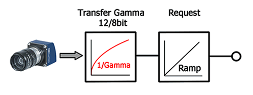
|
| LUTmDirect | Maps an image by applying intensity transformation. |
◆ TMemoryManagerMode
| enum TMemoryManagerMode |
Defines valid modes to operate the memory manager in.
| Enumerator | ||
|---|---|---|
| mmmAuto | 0 | Automatic mode. In this mode the DMA memory is only used as intermediate buffer. The user has no direct access to it instead he get always a copy of the image that resides on the heap. Internally the DMA memory is organized as ring buffer. It decouples the autonomous grabbing of the board from the application. The size of the memory should be big enough to hold as many images as requests are used in the application. |
| mmmPool | 1 | Pool Mode. This mode allows direct access to the DMA memory. So its not necessary for the driver to make copies of the images. This improves the performance of the system. But there is one disadvantage: The partitioning of the DMA memory is fixed and has to be done by the user. The block size must be set to the image size in bytes. Additional the block count must be set. Before these parameters can be changed it must be sure that all ImageBuffers are returned and the grabber is stopped. |
◆ TMemoryManagerPoolMode
◆ TMirrorMode
| enum TMirrorMode |
Defines valid mirror modes.
These enumeration values may be 'ored' together.
| Enumerator | ||
|---|---|---|
| mmOff | 0 | No Mirroring. |
| mmTopDown | 0x1 | The resulting image will be flipped around a horizontal axis. |
| mmLeftRight | 0x2 | The resulting image will be flipped around a vertical axis. |
| mmTopDownAndLeftRight | mmTopDown | mmLeftRight | The resulting image will be both around a horizontal and vertical axis. |
◆ TMirrorOperationMode
| enum TMirrorOperationMode |
◆ TOBJ_HandleCheckMode
| enum TOBJ_HandleCheckMode |
◆ TOBJ_StringQuery
| enum TOBJ_StringQuery |
Valid string query types.
Certain information for an object can be queried as a string with direct construction.
| Enumerator | ||
|---|---|---|
| sqObjName | 0 | The name of the object referenced by HOBJ. |
| sqObjDocString | 1 | The documentation string of the object referenced by HOBJ. |
| sqListContentDescriptor | 2 | The content descriptor of the object referenced by HOBJ.
|
| sqPropVal | 3 | The value of the object referenced by HOBJ.
|
| sqPropFormatString | 4 | The format string of the object referenced by HOBJ.
|
| sqMethParamString | 5 | The parameter list of the object referenced by HOBJ.
The returned string will contain characters giving information about the parameters expected by the method object. The characters have the following meaning:
Examples:
|
| sqObjDisplayName | 6 | The display name of the object referenced by HOBJ.
|
◆ TPayloadType
| enum TPayloadType |
Defines supported payload types.
- Since
- 3.2.0
| Enumerator | ||
|---|---|---|
| ptUnknown | 0 | The framework is not aware of the data type of this request. From the application perspective this can be handled as raw data. However the most likely reason for unknown data is that the request either does not contain any data right now or the last capture operation did fail for any reason.
|
| pt2DImage | 1 | Color or monochrome (2D) image. This request carries pixel data belonging to a single image and maybe some additional chunk data as well.
|
| ptJPEG | 5 | JPEG image data. This request carries JPEG data belonging to a single image.
|
| ptJPEG2000 | 6 | JPEG 2000 image data. This request carries JPEG 2000 data belonging to a single image.
|
| ptH264 | 7 | H.264 image data. This request carries H.264 data belonging to a single image.
|
| ptChunkOnly | 8 | Chunk data only. This request carries chunk data as defined by the corresponding vision standards and no additional payload.
|
| ptMultiPart | 10 | Multi-Part data. This request carries multi-part data as defined by the corresponding vision standards and maybe some additional chunk data as well. In order to access the individual parts forming the full request the buffer part related API can be used.
|
| ptGenDC | 11 | GenDC data. This request carries GenDC data as defined by the corresponding vision standards. In order to access the individual parts forming the full request either the buffer part related API can be used or the full GenDC container can be interpreted by using official header files or knowledge obtained by reading the GenICam™ GenDC standard.
|
◆ TPolarizedDataExtractionInterpolationMode
Defines valid modes for the interpolation mode of polarization data extraction filters.
- Since
- 2.29.0
| Enumerator | |
|---|---|
| primOff | No interpolation. The resulting image therefore will have the same amount of pixels for horizontal or vertical polarization data extraction modes or a reduced number of pixels for all other modes.
|
| primLinear | Linear interpolation. The resulting image therefore will have either 4 times the number of pixels for horizontal or vertical polarization data extraction modes or the same dimensions as the input image for single extraction mode. The additional pixel data will be generated using linear interpolation algorithm
|
◆ TPolarizedDataExtractionMode
Defines valid modes for polarization data extraction filters.
- Since
- 2.29.0
| Enumerator | |
|---|---|
| prmVertical | The pixels will be re-arranged one after the other thus the resulting image will have a width of 'input image width / 2' and a height of 'input image height * 2'. The resulting image will consist of several small images sitting on top of each other. The first image will contain all the upper left pixels from each extraction ROI, the last image all the lower right pixels. The images in between will be extracted line by line and then row by row.
|
| prmHorizontal | The pixels will be re-arranged one after the other thus the resulting image will have a width of 'input image width * 2' and a height of 'input image height / 2'. The resulting image will consist of several small images sitting next each other. The first image will contain all the upper left pixels from each extraction ROI, the last image all the lower right pixels. The images in between will be extracted line by line and then row by row.
|
| prmExtractSingle | The pixel selected by 'PolarizedDataExtractionChannelIndex' will be extracted and forwarded from each region defined by '2 * 2'. The resulting image therefore will have a width equal to 'input image width / 2' and a height equal to 'input image height / 2'
|
| prmMinimumValue | The pixel with the minimum value will be extracted and forwarded from each region defined by '2 * 2'. The resulting image therefore will have a width equal to 'input image width / 2' and a height equal to 'input image height / 2'
|
| prmMeanValue | The mean value of all pixels whose value ranges from 'PolarizedDataExtractionLowerLimit' to 'PolarizedDataExtractionUpperLimit' will be calculated within each region defined by '2 * 2' in the source image and will be forwarded as a single new pixel in the destination image. The resulting image therefore will have a width equal to 'input image width / 2' and a height equal to 'input image height / 2'
|
| prm2By2 | The pixels will be re-arranged in a way the image keeps its original dimension but each polarization angle will afterwards occupy a certain section in the image. The upper left quarter of the resulting image will contain all the upper left pixels from each 2 by 2 pixel region etc.
|
| prmExtractAngle | The angle of the maximum polarization for every '2 * 2' region in the image will be calculated and the resulting value will then be mapped to the value range of the source pixel format. The resulting image therefore will have a width equal to 'input image width / 2' and a height equal to 'input image height / 2'. From each 2 by 2 region (thus 4 input values) a single output value will be calculated and placed into the resulting image. In this mode the output pixel format will be the same as the input pixel format and the resulting value will be mapped to this pixel formats value range thus the maximum angle (180 degree) will correspond the maximum pixel value in this format (e.g. 1023 for ibpfMono10). The angle of the maximum polarization is calculated based the formula:
|
| prmExtractDegree | The degree of the polarization for every '2 * 2' region in the image will be calculated and the resulting value will then be mapped to the value range of the source pixel format. The resulting image therefore will have a width equal to 'input image width / 2' and a height equal to 'input image height / 2'. From each 2 by 2 region (thus 4 input values) a single output value will be calculated and placed into the resulting image. In this mode the output pixel format will be the same as the input pixel format and the resulting value will be mapped to this pixel formats value range thus the maximum polarization will correspond the maximum pixel value in this format (e.g. 1023 for ibpfMono10). The calculation of the degree of the maximum polarization is based the formula:
|
| prmPseudoColorRepresentation | The angle of the maximum polarization and the degree of the polarization for every '2 * 2' region in the image will be calculated and the resulting value will then be mapped to the value range of and 8-bit HSL image. The angle and the degree are calculated as described in prmExtractDegree and prmExtractAngle mode. Afterwards the angle is used as hue and the degree is used as saturation value in the HSL color representation and converted to RGB color representation. The resulting image therefore will have a width equal to 'input image width / 2' and a height equal to 'input image height / 2'. From each 2 by 2 region (thus 4 input values) 2 output values will be calculated and placed into the resulting temporary HSL image. Afterwards this HSL image will transformed back to RGB to generate a pseudo-color image in ibpfRGB888Planar format.
|
![\[\Theta = \frac{1}{2}*atan\left (\left ( P45-P135 \right ); \left (P0 - P90\right )\right ) \]](form_0.png)
![\[\Pi = \frac{\sqrt{\left(P0-P90\right)^{2}+\left(P45-P135\right)^{2}}}{\left(P0+P90\right)}\]](form_1.png)
◆ TRequestImageMemoryMode
Defines valid image modes for request objects.
| Enumerator | |
|---|---|
| rimmAuto | Automatic mode. In this mode the driver will decide what kind of memory will be used, when it will be allocated and when it will be freed. |
| rimmUser | User supplied memory mode. A request in this mode can capture data directly into a user supplied buffer. The user can assign a buffer to each request that has been set into this mode. However some devices require the capture memory to be aligned thus then the buffer supplied by the user must be aligned to the requirements of the driver as well. To find out, which alignment is needed, the property captureBufferAlignment must be queried. |
- Examples
- CaptureToUserMemory.c.
◆ TRequestResult
| enum TRequestResult |
Defines valid result of an image request.
Whenever during the processing of the capture parameters but well before the actual image capture and error is detected the MSB of this enumeration will be set to 1. In this case almost every time the current input parameters can't lead to a correct image and have to be changed.
| Enumerator | ||
|---|---|---|
| rrOK | 0 | This image request has been processed successfully. |
| rrTimeout | 1 | This image request resulted in a timeout. No image has been captured during the allowed period of time. |
| rrError | 2 | An error occurred during the processing of this request. mvBlueFOX specific: This error typically results in some kind of USB transmission problem. The log-file will contain more information in that case. |
| rrRequestAborted | 3 | This request has been aborted either because there are no free internal buffers or the user itself caused this abort e.g. by clearing the request queue. |
| rrFrameIncomplete | 4 | An incomplete frame was transferred. This can have several reasons, however the one most likely is that the transfer channel couldn't cope with the amount of data that was transmitted resulting in parts of the frame or in the worst case the complete frame being lost. This e.g. might happen if several network devices transmit at the same time or a single device (e.g. connected to a PCI bus transfers more data than the PCI bus can pass to the receiving end until a temporary buffer on the device runs full. The log output will contain additional information. If the information is available the property 'MissingData_pc' belonging to that request will contain information about the amount of data missing. Also some of the statistical properties will provide hints about how much data is lost. E.g. the properties 'MissingPacktesRecovered', 'RetransmitCount' and 'MissingDataAverage_pc' might be of interest here. Please note that not every property is supported by every device. |
| rrDeviceAccessLost | 5 | The access to the device has been lost. In this case no further access to the device will succeed. Only closing and re-opening the device will fix this problem. There can be numerous reasons for this error to occur, however the most likely one is that a device, that a timeout register inside the device, that needs to be refreshed constantly by the driver hasn't been refreshed during the timeout period. In this case the device will disconnect itself from the driver. This e.g. can happen if a network device is used and the application is operated in debug mode. For debugging the corresponding timeout register must be set to an appropriate value. |
| rrInconsistentBufferContent | 6 | A complete buffer has been delivered, but it did fail to pass the internal validation check. This e.g. might happen with drivers that transmit buffers that contain more than a pure block of pixel data. Examples for this might be run-length encoded images, or buffers with additional information somewhere in the buffer that will be interpreted by the device driver. This error is most likely a result of a device that doesn't transfer data in the requested format. The log output will contain additional information. |
| rrFrameCorrupt | 7 | The device has reported that an image acquisition did fail on the device side thus BEFORE the data transfer. This e.g. might happen if a device is running low on local memory or because of some other problem detected on the device itself. This result status is just meant for information. The associated buffer will not contain valid image data. |
| rrUnprocessibleRequest | 0x80000000 | This request is not processible. If this flag (the MSB) is set this either indicates that the current input parameters can't be used to capture an image (in that case the result will not be the MSB alone) or that an internal error occurred during the process of this request. |
| rrNoBufferAvailable | rrUnprocessibleRequest | 1 | No free buffer available to process this request. To get more memory either some old requests should be unlocked or the size of the DMA memory (frame grabbers only) could be increased using the tools provided. |
| rrNotEnoughMemory | rrUnprocessibleRequest | 2 | There is not enough memory available to the driver to process the current image request. To get more memory either some old requests should be unlocked or the size of the DMA memory (frame grabbers only) could be increased using the tools provided. Another possibility might be, that the process currently hosting the application cannot map all the capture memory requested by the application. In this case adding more memory to the system might solve the problem. Please note that when running on a 32 bit system no more than 2 GB of RAM can be used by a single process, thus applications demanding a lot of memory might still not run then. In this case only reducing the number of request buffers will help. |
| rrCameraNotSupported | rrUnprocessibleRequest | 5 | The current camera description is not supported by the capture device. This error code currently is relevant for frame grabbers only and might occur e.g. when selecting a MEDIUM CameraLink® camera description for a grabber, that only supports BASE cameras. |
| rrDataAcquisitionNotSupported | rrUnprocessibleRequest | 7 | The device does not support capturing data in the current configuration. This error code will occur if a request has been sent to a device that does not support the acquisition of data. This can e.g. be the case
|
◆ TRequestState
| enum TRequestState |
Defines the current state of this Request.
| Enumerator | |
|---|---|
| rsIdle | This Request is currently unused. |
| rsWaiting | This Request has been sent into the framework's image request queue and currently awaits processing. |
| rsCapturing | This Request is currently being processed. |
| rsReady | This Request has been processed. The user is now responsible for this request. Before this Request is not unlocked again it can't be used by the framework. A Request in this state can safely be processed by the user. Its data will remain valid until either the Request is unlocked by the user or the device is closed. |
| rsBeingConfigured | This Request is currently in configuration mode. In this mode certain properties of the request object will become writeable, which e.g. will allow the user to pass a capture buffer to the request object. The user is now responsible for this request. Before this Request is not unlocked again it can't be used by the framework. |
◆ TScalerInterpolationMode
◆ TScalerMode
| enum TScalerMode |
◆ TUserDataAccessRight
| enum TUserDataAccessRight |
Defines valid flags for controlling the user access rights to the user data that can be stored in the devices non-volatile memory.
| Enumerator | ||
|---|---|---|
| udarRead | 0x1 | The user has read rights for this entry. |
| udarWrite | 0x2 | The user has principle write rights for this entry. If udarPassword is not set for this entry or the corresponding password has been set correctly, the user can modify the corresponding entry. |
| udarRW | udarRead | udarWrite | |
| udarPassword | 0x4 | A password is needed to modify this entry. Even if udarWrite is specified the user can only modify this entry if the correct password has been set. |
| udarFull | udarRW | udarPassword | Combines all other flags. |
◆ TUserDataReconnectBehaviour
Defined valid values for the behaviour of the user data when a device has been disconnected and reconnected within a running process.
| Enumerator | |
|---|---|
| udrbKeepCachedData | Keep the data currently buffered in the properties describing the user data. When the user data has been modified on another machine this will result in a loss of that data once this buffered data is written back to the devices non-volatile memory. |
| udrbUpdateFromDeviceData | Updates the properties describing the user data with the fresh data as read from the devices non-volatile memory. This might result in the loss of data that has been edited but NOT written to the devices non-volatile memory if this data differs from the current data stored in the devices non-volatile memory. |
◆ TVideoCodec
| enum TVideoCodec |
Defines valid video codecs that might be supported by the underlying video compression engine.
| Enumerator | ||
|---|---|---|
| vcMPEG2 | 2 | MPEG2. Recommend file extension for this codec: .m2v Supported input pixel formats for this video codec: |
| vcH264 | 27 | H264. Recommend file extension for this codec: .mp4 Supported input pixel formats for this video codec: |
| vcH265 | 173 | H265. Recommend file extension for this codec: .mp4 Supported input pixel formats for this video codec: |
◆ TVideoStandard
| enum TVideoStandard |
Defines valid video standards that might be supported by a video capture device.
| Enumerator | |
|---|---|
| vsCCIR | CCIR video signal: Grey, 50 fields per second, 625 lines. |
| vsRS170 | RS 170 video signal: Grey, 60 fields per second, 525 lines. |
| vsPALBGH | PAL video signal: Color, 50 fields per second, 625 lines. |
| vsNTSCM | NTSC video signal: Color, 60 fields per second, 525 lines. |
| vsSDI480i | SDI video signal: 60 fields per second, 480 lines, interlaced. |
| vsSDI576i | SDI video signal: 50 fields per second, 576 lines, interlaced. |
| vsSDI720p | SDI video signal: Different frame rates, 720 lines, progressive. |
| vsSDI1080i | SDI video signal: Different frame rates, 1080 lines, interlaced. |
| vsSDI1080p | SDI video signal: Different frame rates, 1080 lines, progressive. |
◆ TWhiteBalanceCalibrationMode
Defines valid white balance calibration modes.
| Enumerator | ||
|---|---|---|
| wbcmOff | 0 | Do not perform calibration, current values will be used. |
| wbcmNextFrame | Use the next image to perform the white balance calibration. This is defined for bayer color sensors only. | |
| wbcmContinuous | Do a continuous white balance calibration. | |
◆ TWhiteBalanceParameter
Defines valid parameter sets selectable via the WhiteBalance property.
| Enumerator | ||
|---|---|---|
| wbpTungsten | 0 | A set of constant parameters optimised for scenes illuminated by tungsten light sources. |
| wbpHalogen | A set of constant parameters optimised for scenes illuminated by halogen light sources. | |
| wbpFluorescent | A set of constant parameters optimised for scenes illuminated by fluorescent light sources. | |
| wbpDayLight | A set of constant parameters optimised for scenes illuminated by day light. | |
| wbpPhotoFlash | A set of constant parameters optimised for scenes illuminated by photo flash light sources. | |
| wbpBlueSky | A set of constant parameters optimised for scenes illuminated by day light and perfect weather. | |
| wbpUser1 | A parameter set which can be modified by the user. | |
| wbpUser2 | A parameter set which can be modified by the user. | |
| wbpUser3 | A parameter set which can be modified by the user. | |
| wbpUser4 | A parameter set which can be modified by the user. | |