Loading...
Searching...
No Matches
mvBlueFOX3-2205 / [BVS CA-SF2|BVS CA-SF5|BF3-5M]-0205Z (20.5 Mpix [5544 x 3692])
Introduction
The sensor is a back-illuminated rolling shutter, i.e. the image is acquired through the back side without any obstacles like wiring or circuits. Therefore, a wider range of light is collected on the photo-diode.
| Feature | Description |
| Manufacturer | Sony |
| Sensor name | IMX183 |
| Max. frames per second | 22 |
| Device Structure | CMOS image sensor |
| SNRmax [dB]1/ | 41.6 |
| DNR (normal / HDR) [dB]1/ | 71.5 / - |
| Image size | 1 |
| Number of effective pixels | 5544 (H) x 3692 (V) |
| Unit cell size | 2.4µm (H) x 2.4µm (V) |
| ADC resolution / output | 12 bit → 8/10/(12) |
1 Measured accord. to EMVA1288 with gray scale version of the camera
Shutter modes
The sensor offers several shutter modes:
- rolling shutter (mvShutterMode =
"mvRollingShutter"), - rolling shutter flash (mvShutterMode =
"mvRollingShutterFlash"), and - global reset release shutter (mvShutterMode =
"mvGlobalReset").
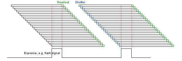
With the rolling shutter the lines are exposed for the same duration, but at a slightly different point in time.
- The exposure time which is set corresponds to the exposure time of each line.
- The exposure signal corresponds to the exposure of the first line.
- Note
- Moving objects together with a rolling shutter can cause a smear in moving objects.
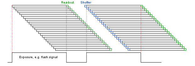
With the rolling shutter flash
- The exposure time which is set corresponds to the time where all lines are exposed simultaneously.
- The exposure signal corresponds to the time where the last line starts until the first line ends.
The global reset release shutter starts the exposure of all rows simultaneously and the reset to each row is released simultaneously, too. However, the readout of the lines is equal to the readout of the rolling shutter: line by line:
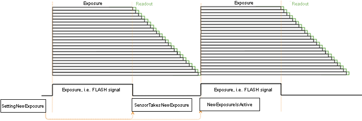
- Note
- This means, the bottom lines of the sensor will be exposed to light longer! For this reason, this mode will only make sense, if there is no extraneous light and the flash duration is shorter or equal to the exposure time.
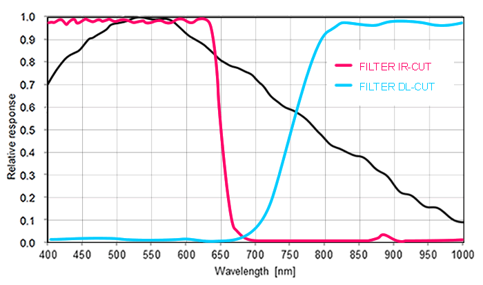
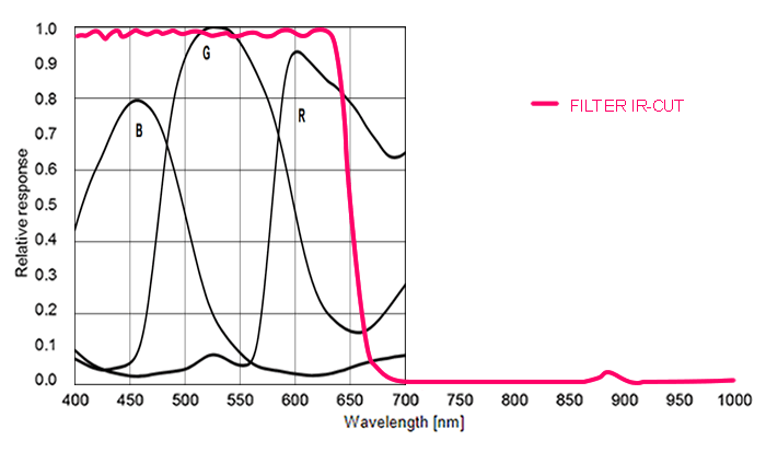
Spectral Sensitivity
Timings
| Name | Value |
| InternalLineLength | 876 |
| VerticalBlankLines | 37 |
| SensorInClock | 72 MHz |
| NumberOfLVDS | 8 |
Free running mode
In free running mode, the sensor reaches its maximum frame rate. This is done by overlapping erase, exposure and readout phase. The sensor timing in free running mode is fixed, so there is no control when to start an acquisition. This mode is used with trigger mode Continuous.
To calculate the maximum frames per second (FPSmax) in free running mode you will need following formula:
             (InternalLineLength / SensorInClock) * VerticalBlankLines       ImageHeight * (InternalLineLength / SensorInClock)
FrameTime =  ---------------------------------------------------------   +   --------------------------------------------------
                                 1000                                                              1000
If exposure time is lower than frame time:
                 1
FPS_max =  ------------
            FrameTime
If exposure time is greater than frame time:
                 1
FPS_max =  --------------
            ExposureTime
Connection
Frame rate calculator
- Note
- The calculator returns the max. frame rate supported by the sensor. Please keep in mind that it will depend on the interface and the used image format if this frame rate can be transferred.
- Note
- The exposure time step width is limited to the sensor's row time of 12.16 us and therefore
- auto exposure with very low exposure times will perform with relatively large increments and
- exposure mode = TriggerWidth (if available) will perform with a jitter corresponding to the row time.
The following trigger modes are available:
| Setting (GenICam) | Mode / Setting (obsolete "Device Specific") | Description |
"TriggerSelector = FrameStart" "TriggerMode = Off" | Continuous | Free running, no external trigger signal needed. |
"TriggerSelector = FrameStart" "TriggerMode = On" "TriggerSource = Software" "ExposureMode = Timed" To trigger one frame execute the TriggerSoftware@i command then. | OnDemand | Image acquisition triggered by command (software trigger). |
"TriggerSelector = AcquisitionActive" "TriggerMode = On" "TriggerSource = <desired Line>" "TriggerActivation = LevelLow" "ExposureMode = Timed" | OnLowLevel | Start an exposure of a frame as long as the trigger input is below the trigger threshold. (No FrameTrigger!) |
"TriggerSelector = AcquisitionActive" "TriggerMode = On" "TriggerSource = <desired Line>" "TriggerActivation = LevelHigh" "ExposureMode = Timed" | OnHighLevel | Start an exposure of a frame as long as the trigger input is above the trigger threshold. (No FrameTrigger!) |
"TriggerSelector = FrameStart" "TriggerMode = On" "TriggerSource = <desired Line>" "TriggerActivation = FallingEdge" "ExposureMode = Timed" | OnFallingEdge | Each falling edge of trigger signal acquires one image. |
"TriggerSelector = FrameStart" "TriggerMode = On" "TriggerSource = <desired Line>" "TriggerActivation = RisingEdge" "ExposureMode = Timed" | OnRisingEdge | Each rising edge of trigger signal acquires one image. |
"TriggerSelector = FrameStart" "TriggerMode = On" "TriggerSource = <desired Line>" "TriggerActivation = AnyEdge" "ExposureMode = Timed" | OnAnyEdge | Start the exposure of a frame when the trigger input level changes from high to low or from low to high. |