Loading...
Searching...
No Matches
Important Information

General Notes
Activities such as installation, connection and commissioning may only be carried out by qualified personnel.
Qualified personnel are persons whose technical training, knowledge and experience as well as knowledge, of the relevant regulations allow them to assess the work assigned to them, recognize possible hazards and take appropriate safety measures.
The operator is responsible for ensuring that local safety regulations are observed. In particular, the operator must take steps to ensure that a defect in the product will not result in hazards to persons or equipment.
The product must not be opened, modified, or changed. In case of defects and unrepairable malfunctions of the product, it must be taken out of operation and secured against unauthorized use.
Additionally,
- We cannot and do not take any responsibility for the damage caused to you or to any other equipment connected to the Balluff/MATRIX VISION device. Similarly, warranty will be void, if a damage is caused by not following the manual.
- Handle your Balluff/MATRIX VISION device with care. Do not misuse it. Avoid shaking, striking, etc. The Balluff/MATRIX VISION device could be damaged by faulty handling or shortage.
- Do not modify the Balluff/MATRIX VISION device or use it with external covers removed. These may cause failure, void any warranties and pose a safety hazard.
- Do not attempt to disassemble Balluff/MATRIX VISION device.
- Do not use accessories not recommended by Balluff/MATRIX VISION as they may cause hazards.
- The Balluff/MATRIX VISION device should be situated away from heat sources such as radiators, heat registers, stoves, or other products (including amplifiers) that produce heat.
- When installing or removing a lens, take care that water or dust does not enter the inside of the Balluff/MATRIX VISION device.
Operating Considerations
Power supply
- Use the device with a suitable power supply with following specifications: 12 V, 2.5 A ± 5% or 24 V, 1.25 A, ± 5%.
Electrostatic Discharge (ESD)
Handle with care and avoid damage of electrical components by electrostatic discharge (ESD) especially when working without housing:
- Discharge body static (contact a grounded surface and maintain contact).
- Avoid all plastic, vinyl, and styrofoam (except anti-static versions) around printed circuit boards.
- Do not touch components on the printed circuit board (PCB) with your hands or with conductive devices.
Overheating and Cooling
- Attention
- "Overheating"
Heat can affect the image quality, damage the device, or shorten the life of the device. Provide adequate dissipation of heat.
Balluff recommends the following for proper heat dissipation:
- Always take measures to ensure cooling.
- Monitor the temperature of the device to activate cooling measures (properties and mechanisms are available: Working with the temperature sensors).
- Only operate the device in mounted condition.
- Attach the device to a sufficiently large heat sink.
- Keep the heat transition resistance as low as possible.
- In mounted condition, it is also possible - or in addition - to cool the device using a fan.
- For board-level devices recommend to use or configure the device with a thermal conduction plate.
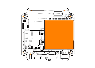
For heat dissipation of the "BVS CA-SF2-xxxxxx-100000", we recommend the surface of the FPGA (orange area of the following figure):
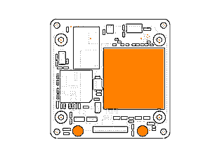
For heat dissipation of the "BVS CA-SF5-xxxxxx-100010", we recommend the surface of the FPGA (orange areas of the following figure):
- Note
- The FPGA area of Rev. 2.xx models has a different height (-0.5 mm).
- The mainboard's temperature may not exceed 80 °C!
Installation
Avoid installing or storing the Balluff/MATRIX VISION device in the following environments:
- Environments exposed to direct sunlight, rain or snow.
- Environments where combustible or corrosive gas exists.
- Excessively warm or cold environment (Operating ambient temperature: 0 to 45 °C)
- Humid or dusty environment.
- Place subjected to excessive vibration or shock.
- Environment exposed to strong electric or magnetic field.
- It is recommended to mount the Balluff/MATRIX VISION device on a thermoconducting surface such as aluminum or other metals rather than plastic or wood.
- Please contact manufacturer or local distributor if you want to use additional enclosures for higher ingress protection.
- Do not aim the Balluff/MATRIX VISION device at the sun or other very strong light sources, otherwise you can destroy the image sensor.
- Be careful when bending the flex cable of the BVS CA-SF1-xxxxxx-100000. The minimum bending radius is approx. 3 mm.
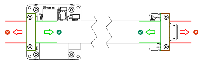
- Because the connector of the rigid-flex extension cable (BFE-FLEX) of the BVS CA-SF3-xxxxxx-100020 or BVS CA-SF5-xxxxxx-100010 can be connected in both ways you have to check if it is connected the right way and that is: The cable must be lead away over each board
- Confirm the power is off before connecting or disconnecting a signal cable. Grap connectors by the body, not the attached wires.
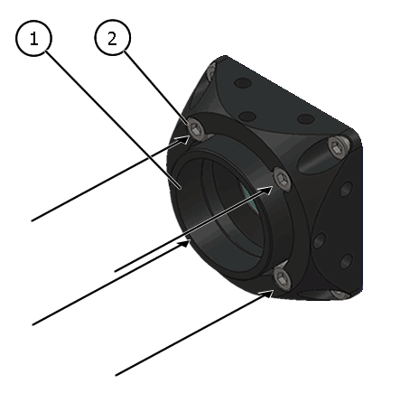
Adjusting the C-mount type 1 with adjustable backfocus
The C-mount type 1 lensholder allows a precise adjustment of the backfocus of the C-mount by means of a backfocus ring which is threaded into the C-mount and is secured by a lock nut ring which itself is secured by two screws. The mechanical adjustment of the imaging device is important in order to achieve a perfect alignment with the focal point of the lens. This adjustment is made before leaving the factory to conform to the standard of 17.526 mm (in air) and should normally not require adjustment in the field. However, if the backfocal plane of your lens does not conform to the C-mount backfocus specification or if you have e.g. removed the IR-CUT filter, renewed adjustment may be required.
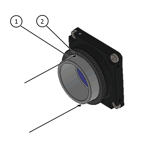
How to proceed:
- Loosen screws (location as shown above by arrows) of the lock nut ring with an Allen key (0.9 x 50).
- Loosen the lock nut ring.
- With the lens set to infinity or a known focus distance, set the device to view an object located at "infinity" or the known distance.
- Rotate the C-mount ring and lens forward or backwards on its thread until the object is in sharp focus.
- Note
- Be careful that the lens remains seated in the C-mount.
- Once focus is achieved, tighten the lock nut ring, then tighten the two locking screws of the lock ring without applying excessive torque.
Adjusting the C-mount type 2 with factory-set backfocus
The C-mount type 2 lensholder does not support backfocus adjustment. However, with the four screw locks at the front of the lens holder, it is possible to rotate the C-mount ring.
- Note
- In combination with BVS CA-SF2-0089Z and BVS CA-SF2-0124Z the C-mount lens holder has to look upwards during the adjusting. Otherwise the aperture can jump out of the guide.
- Loosen the screw locks with an Allen key (2.5 mm).
- With it, you can adjust the position of the lens, for example, to have the scale or the locking screws of the lens at a specific position.
- Note
- Always tighten the screws in a diagonal sequence first slightly and then little by little to a torque of 0.9 Nm.
Operation
- Observe that flammable objects, water or metal do not enter the Balluff/MATRIX VISION device interior. These may lead to failure or accident.
- Stop using the Balluff/MATRIX VISION device at the approach of electrical storm (thunder audible). Protect the Balluff/MATRIX VISION device from rain if using it outdoors.
- In the event of abnormal functioning, switch off the Balluff/MATRIX VISION device and disconnect the power cord. Contact Balluff (suppo.nosp@m.rt.d.nosp@m.e@bal.nosp@m.luff.nosp@m..de).
Cleaning
- Use a blower or a lens brush to remove dust on the lens or the optical filter.
- Do not disassemble front flange.
- Clean case with dry soft cloth. Use neutral detergent liquid if needed; wipe the cover with dry cloth.
- Do not use benzene, thinner, alcohol, liquid cleaner or spray-type cleaner.
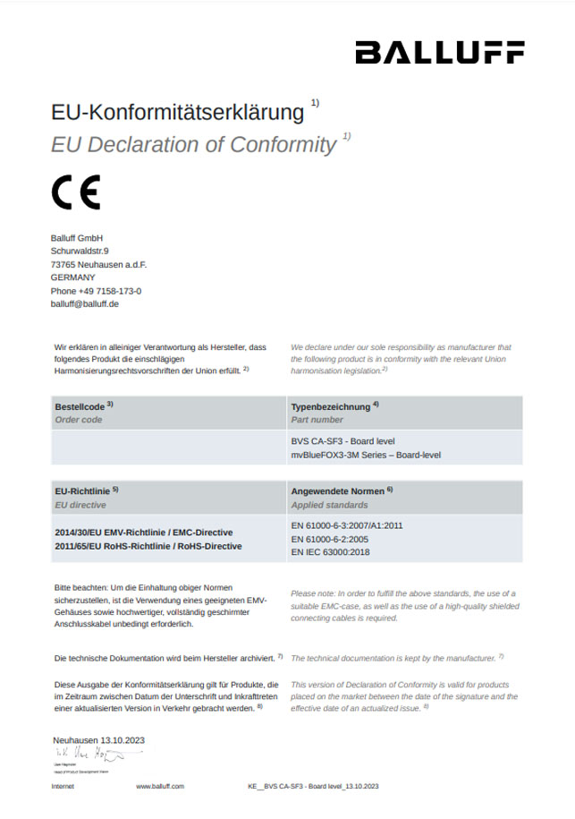
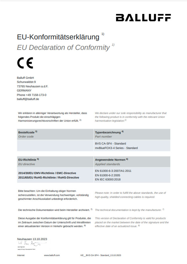
Conformity

| Every BVS CA-SF device is in conformity with all applicable essential requirements necessary for CE marking. It corresponds to the EU EMC guideline 2014/30/EU based on the following harmonized standards Electromagnetic compatibility (EMC)
|

| BVS CA-SF2 and BVS CA-SF4, both without I/Os (ULUS applies with I/Os.) |

| |

| Balluff/MATRIX VISION corresponds to the EU guideline WEEE 2002/96/EG on waste electrical and electronic equipment and is registered under WEEE-Reg.-No. DE 25244305. |
| RoHS | All units delivered are RoHS compliant. |
| IP30 1 | BVS CA-SF |
1 not evaluated by UL

Additional notices
For customers in the U.S.A.

| Class B |
This equipment has been tested and found to comply with the limits for a Class B digital device, pursuant to Part 15 of the FCC Rules. These limits are designed to provide reasonable protection against harmful interference when the equipment is operated in a residential environment. This equipment generates, uses, and can radiate radio frequency energy and, if not installed and used in accordance with the instruction manual, may cause harmful interference to radio communications. However there is no guarantee that interferences will not occur in a particular installation. If the equipment does cause harmful interference to radio or television reception, the user is encouraged to try to correct the interference by one or more of the following measures:
- Reorient or relocate the receiving antenna.
- Increase the distance between the equipment and the receiver.
- Use a different line outlet for the receiver.
- Consult a radio or TV technician for help.
You are cautioned that any changes or modifications not expressly approved in this manual could void your authority to operate this equipment. The shielded interface cable recommended in this manual must be used with this equipment in order to comply with the limits for a computing device pursuant to Subpart B of Part 15 of FCC Rules.
For customers in Canada
This apparatus complies with the Class B limits for radio noise emissions set out in the Radio Interference Regulations.
Pour utilisateurs au Canada
Cet appareil est conforme aux normes classe B pour bruits radioélectriques, spécifiées dans le Règlement sur le brouillage radioélectrique.