Introduction
The BVS CA-SF2-0051P / mvBlueFOX3-2051p (5.1 Mpix [2464 x 2056]) sensor is equipped with a polarization filter. So every '2 * 2' pixel area is sensitive for polarized light with the angles 0, 90, 135 and 45 degree. In previous versions, you could display the information from these 4 directions in 4 images, each image showing just the one pixel of the '2 * 2' area with the same filtering direction.
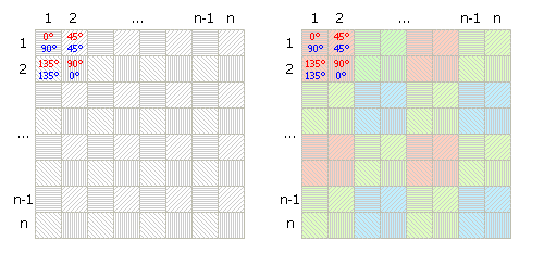
Since version 2.38.0 we support the calculation of the main polarization angle for each '2 * 2' pixel area. Additionally it is possible, to display also the degree of the polarized beam. The resulting image will have a width equal to 'input image width / 2' and height equal to 'input image height / 2'. From each 2 by 2 pixel area a single output value will be calculated.
Polarization value calculation
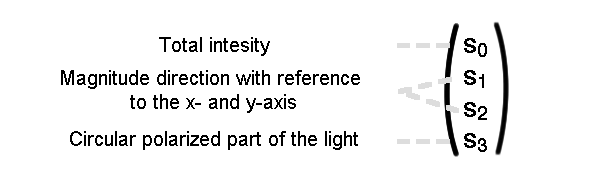
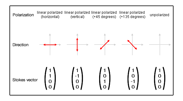
First we calculate the Stokes parameters  ,
,  and
and  for each 2 by 2 pixel area. Since we just filter for linear polarized light, the circular parameter
  will not be used.
-
, the total intensity of the beam, is calculated with:
 , with
  : pixel intensity with 0 degree polarization filter,
  : 90 degree polarization filter.
 -
, the intensity with 0 (horizontal) and 90 (vertical) degree polarization angle.

-
, the intensity with 45 and 135 degree polarization angle.
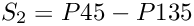 , with
  : pixel intensity with 45 degree polarization filter,
  : 135 degree polarization filter.
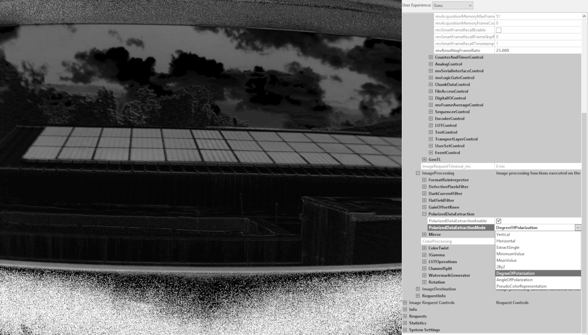
Degree of polarization
The degree of polarization  describes the fraction of the ordered part of the wave. The higher this value, the more polarized is the wave in one single direction. is calculated one time for each 2 by 2 pixel area of an image.
![\[\Pi = \frac{\sqrt{\left(P0-P90\right)^{2}+\left(P45-P135\right)^{2}}}{\left(P0+P90\right)}\]](form_12.png)
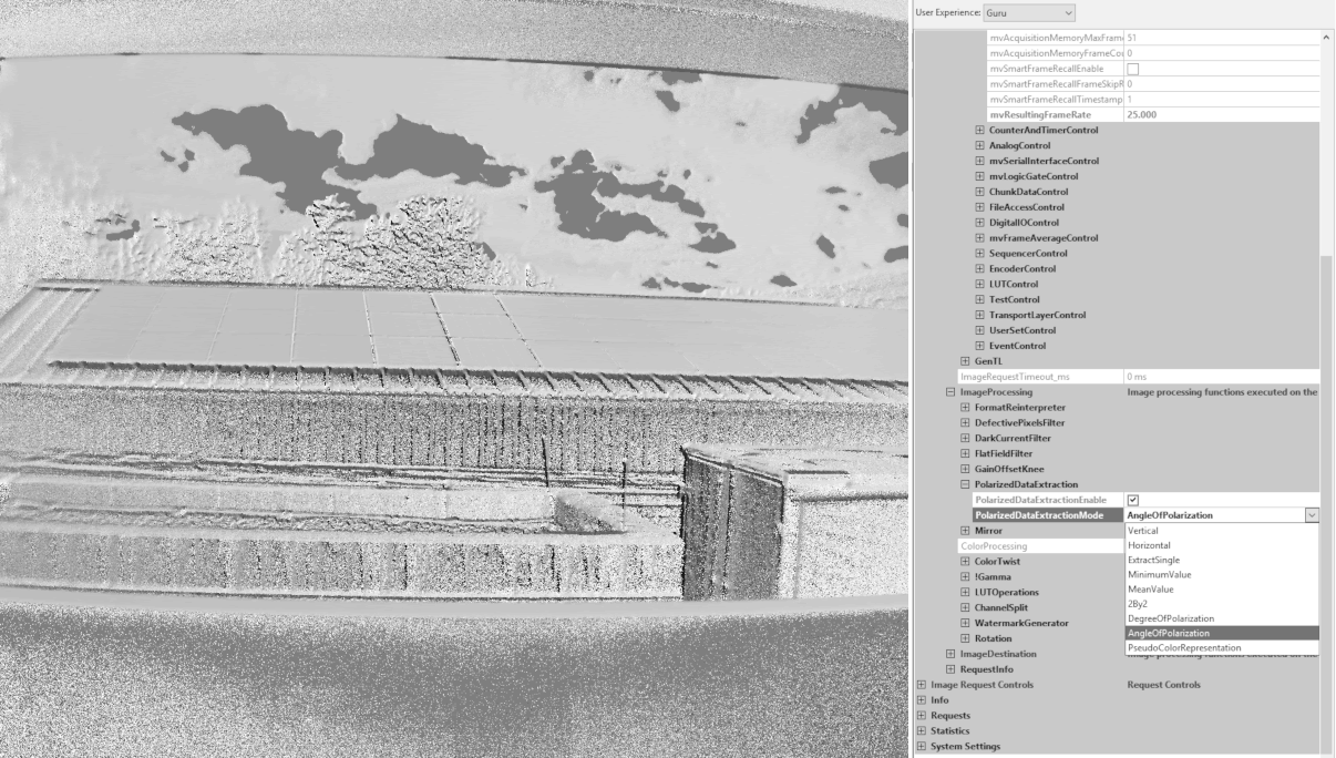
Angle of polarization
The angle of polarization  describes the angle of the maximum polarization, it ranges from 0 to 180 degree. Like , is also calculated one time for each 2 by 2 pixel area.
![\[\Theta = \frac{1}{2}*atan\left (\left ( P45-P135 \right ); \left (P0 - P90\right )\right ) \]](form_14.png)
Image Representation
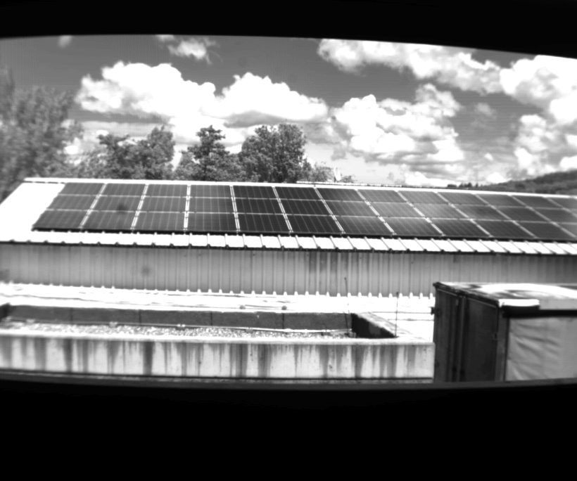
After the calculation of and for each 2 by 2 pixel area, there are some ways on how these values can be displayed. The following images show all the same scene, first the raw pixel values and afterwards some pictures with computed values.
The first possibility is, to display the angle of polarization. Therefore the resulting value for will be mapped to the output pixel format, for example 180 degree would result in a maximum pixel value of 1023 for a 10-bit format.
Another possibility is to display the degree of polarization. The value for will be mapped to the output pixel format, for example a maximum polarized beam with = 1 would result in a maximum pixel value of 255 for a 8-bit format.
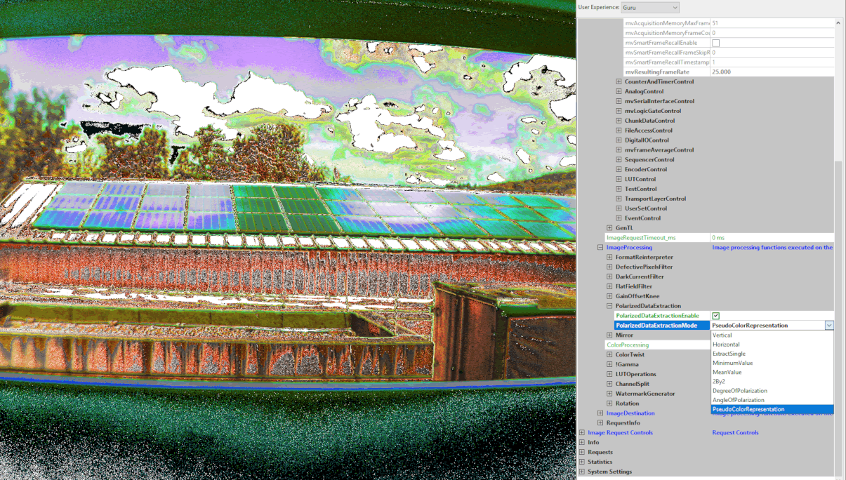
The third way is to display the angle and the degree of polarization in a single image as a pseudo color representation. Therefore both values will be mapped to a 8-bit HSL image. The angle value represents the hue and the degree will be mapped to the saturation value of the image. Finally the HSL image is converted to RGB and displayed.