Loading...
Searching...
No Matches
Processing triggers from an incremental encoder
Introduction
The following figure shows the principle of an incremental encoder:
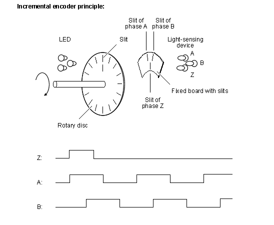
This incremental encoder will send a A, B, and Z pulse. With these pulses there are several ways to synchronize an image with an incremental encoder.
Using ImpactControlCenter and Event Control
To create an external trigger event by an incremental encoder, please follow these steps:
-
Connect the incremental encoder output signal A, for example, to the digital input 0 ("Line4") of the BVS CA-SF .
This line counts the forward pulses of the incremental encoder. -
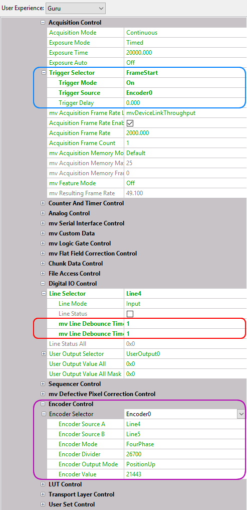
Depending on the signal quality, it could be necessary to set a debouncing filter at the input (red box in Figure 3):
Adapt in "Setting → Base → Camera → GenICam → Digital I/O Control" the "Line Selector" to "Line4" and set "mv Line Debounce Time Falling Edge" and "mv Line Debounce Time Rising Edge" according to your needs. - Set the trigger "Setting → Base → Camera → GenICam → Acquisition Control → Trigger Selector" "FrameStart" to the "Encoder0" ("Trigger Source") signal.
- Then set "Setting → Base → Camera → GenICam → Encoder Control → Encoder Selector" to "Encoder0" and
-
adapt the parameters to your needs.
- See also
- Encoder Control
- Note
- The max. possible frequency is 5 KHz.
Programming the Encoder Control
#include <mvIMPACT_CPP/mvIMPACT_acquire_GenICam.h>

  // more code
  GenICam::EncoderControl ec( pDev );
  ec.encoderSelector.writeS( "Encoder0" );
  ec.encoderSourceA.writeS( "Line4" );
  ec.encoderMode.writeS( "FourPhase" );
  ec.encoderOutputMode.writeS( "PositionUp" );
  // more code
Using ImpactControlCenter and Counter
It is also possible to use Counter and CounterEnd as the trigger event for synchronizing images with an incremental encoder
To create an external trigger event by an incremental encoder, please follow these steps:
-
Connect the incremental encoder output signal A, for example, to the digital input 0 ("Line4") of the BVS CA-SF .
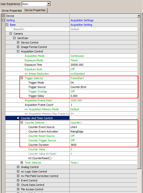
This line counts the forward pulses of the incremental encoder. - Set "Setting → Base → Camera → GenICam → Counter and Timer Control → Counter Selector" to "Counter1" and
- "Counter Event Source" to "Line4" to count the number of pulses e.g. as per revolution (e.g. "Counter Duration" to 3600).
- Then set the trigger "Setting → Base → Camera → GenICam → Acquisition Control → Trigger Selector" "FrameStart" to the "Counter1End" ("Trigger Source") signal.
To reset "Counter1" at Zero degrees, you can connect the digital input 1 ("Line5") to the encoder Z signal.