- Note
- In Ubuntu releases newer than Ubuntu 17.04 (Desktop and Server) network configuration is managed by netplan.io instead of /etc/network/interfaces. Netplan is a powerful tool which uses the information provided in yaml (a human-readable data-serialization language) files for netplan to create configuration files for NetworkManager or system-networkd within their own syntax. A detailed description how to setup the NIC will be available at each step of the following list if the settings could be applied using netplan.
- See also
- More details regarding netplan can be found here:
Receive/Transmit Buffers
A sufficient amount of kernel socket buffer for receiving and transmitting network packets is crucial for a flawless operation!
The following table explains the important settings and recommended values.
| Setting | Value | Description |
| net.core.wmem_max | 16777216 | Maximum memory size of a socket buffer for sending in bytes |
| net.core.rmem_max | 16777216 | Maximum memory size of a socket buffer for receiving in bytes |
| net.core.netdev_max_backlog | 10000 | Maximum number of packets which can be buffered if the kernel does not manage to process them as fast as they are received |
| net.ipv4.udp_mem | 10240, 87380, 16777216 | Minimum, Default and Maximum memory size of a UDP socket buffer for receiving and sending data in bytes |
Usually when receiving TCP traffic on a bad connection the transmission speed simply goes down. For GigE Vision™ UDP streaming the transmission will always run at a dedicated, guaranteed speed and that speed is usually higher than any other network streams speed in a given system. As the operating system not always has a free timeslot available for reporting a network packet to the upper software layer it might have to store a certain amount of packets for a certain period of time. This will be done in the memory block described by the above 3 parameters for sending and receiving data.
To set those values, you have to
-
create the file
/etc/sysctl.d/62-buffers-performance.confand -
add the following lines to this file to increase the network buffers to prevent incomplete frames and fine-tune reverse-path-filtering to allow for discovery of GigE Vision™ cameras with bad network configurations:
net.core.wmem_max=16777216
net.core.rmem_max=16777216
net.core.wmem_default=16777216
net.core.rmem_default=16777216
net.core.netdev_max_backlog=10000
net.ipv4.udp_mem=10240 87380 16777216
net.ipv4.conf.all.rp_filter=2
net.ipv4.conf.default.rp_filter=2
-
Afterwards, reboot the system or enter
sudo sysctl -p /etc/sysctl.d/62-buffers-performance.conf.
- See also
- For more information about Linux network tuning, please have a look at
http://www.cyberciti.biz/faq/linux-tcp-tuning/.
Maximum Transmission Unit (MTU) / Jumbo Frames
- By running ifconfig you can check the current MTU of the network interface.
-
Usually it is best to increase the MTU to the highest value supported by all network components which are within the transmission chain for a better performance. You can set this value permanently in the network configuration GUI (see the image below).
ifconfig - Ethernet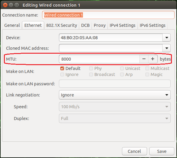
- Reboot the system. Afterwards, you can verify the configured MTU by running ifconfig again.
The camera sets the MTU to the maximum value automatically given by the NIC or switch and supports a maximum MTU of 8K. You can manually change the network packet size the camera uses for transmitting data using this property: "Setting → Base → Camera → GenICam → Transport Layer Control → Gev Stream Channel Selector → Gev SCPS Packet Size":
- Note
- Since the BVS CA-GT family supports 16k packets for using these devices NICs and switches supporting 16k packets as well are recommended.
As a general rule of thumb it can be said, that the higher the MTU, the better the overall performance, as less network packets are needed to transmit a full image, which results in less overhead that arises from the handling of each arriving network packet in the device driver etc. However every component involved in the data transmission (that includes every switch, router and other network component, that is installed in between the device and the system receiving the packets) must support the MTU or packet size, as otherwise the first component not supporting the packet size will silently discard all packets, that are larger than the component can handle. Thus the weakest link here determines to overall performance of the full system!
- Note
- There is no need to set the transfer packet size manually. By default Impact Acquire will determine the maximum possible packet size for the current network settings automatically when the device is initialised. However again the weakest link determines this packet size thus NICs should be chosen and configured appropriately and the same goes for switches!
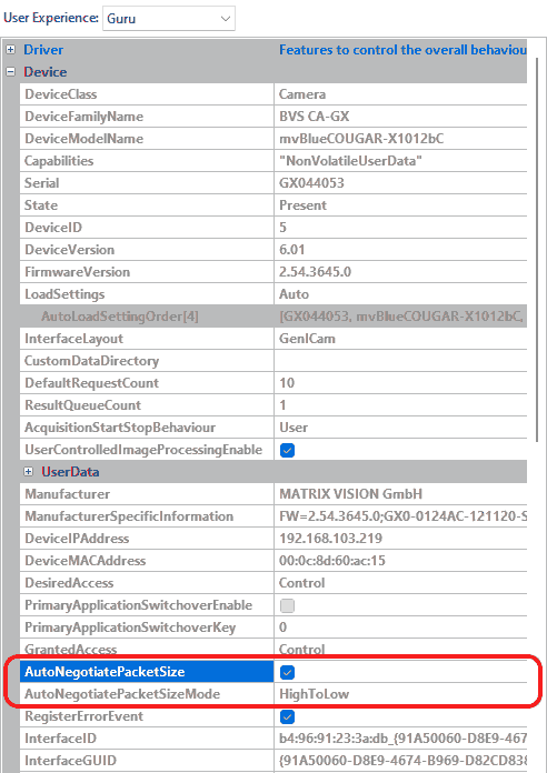
The behavior of the auto negotiation algorithm can be configured manually or to disable it completely if needed. The AutoNegotiatePacketSize property determines if Impact Acquire should try to find optimal settings at all and the way this is done can be influenced by the value of the AutoNegotiatePacketSizeMode property. The following modes are available:
| Value | Description |
| HighToLow | The MTU is automatically negotiated starting from the NICs current MTU down to a value supported |
| LowToHigh | The negotiation starts with a small value and then tries larger values with each iteration until the optimal value has been found |
- Note
- All components belonging to the network path (device, network interface card, switches, ...) will affect the MTU negotiation as every device will support the negotiated value.
To disable the MTU auto negotiation just set the AutoNegotiatePacketSize property to "No".
- Note
- Manually setting the packet size should only be done if
- auto-negotiation doesn't work properly
- there are very good (e.g. application-specific) reasons for doing so
Maximum transmission unit (MTU) / Jumbo Frames using netplan
- Note
- This chapter applies to Ubuntu version 17.10 and newer only.
To configure the MTU without using the NetworkManagerGUI there is as well the possibility to use netplan for configuration. The following sample configuration for netplan will illustrate how the MTU is configured to a reasonable value.
- Note
- The following example assumes that the system has a network interface 'enp0s8' which needs to be configured and the renderer NetworkManager is used on the system!
network:
    version: 2
    renderer: NetworkManager
    ethernets:
        enp0s8:
            mtu: 8020
After applying the configuration using the "netplan apply" command, the configuration will be used.
IPv4 addressing
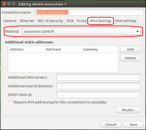
"DHCP"
Connecting the camera via DHCP (e.g. when connecting the camera through a network switch): set the IPv4 addressing method of the host's network controller as DHCP in the IPv4 configuration. Reboot the system afterwards.
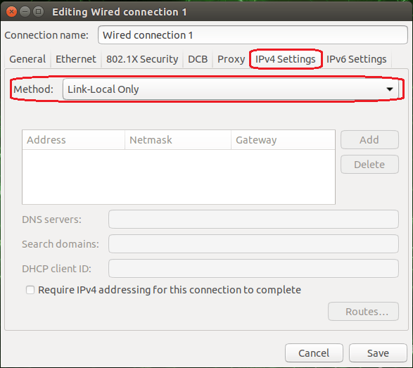
"LLA (Link-Local Address)"
IPv4 addressing using netplan
- Note
- This chapter applies to Ubuntu version 17.10 and newer only.
To configure the network interface for the correct IPv4 ranges the following samples will show different options. Depending on the existing configuration the shown samples might need to be integrated into existing configuration files.
- Note
- The following example assumes that the system has a network interface 'enp0s8' which needs to be configured and the renderer NetworkManager is used on the system!
The following sample shows how the NIC is configured to negotiate its IPv4 address using link-local addressing.
Configuring NIC for link-local addressing
network:
    version: 2
    renderer: NetworkManager
    ethernets:
        enp0s8:
            link-local: [ ipv4 ]
The following sample shows how the NIC is configured to obtain its IPv4 address from a DHCP server.
Configuring NIC for DHCP
network:
    version: 2
    renderer: NetworkManager
    ethernets:
        enp0s8:
            dhcp4: true
The following sample shows how the NIC is configured to use a static IPv4 address.
Configuring NIC with a static IP address
network:
    version: 2
    renderer: NetworkManager
    ethernets:
        enp0s8:
            addresses:
                - 192.168.0.2/24
After applying the configuration using the "netplan apply" command, the configuration will be used.
Link Aggregation, Teaming Or Bonding (GigE Vision™ Devices With Multiple NICs (BVS CA-GX2))
The BVS CA-GX2 Dual-GigE camera needs a network interface card with two network interfaces which support so-called "Link Aggregation" or "bonding".
To bond the network interface, the following description assumes that your system has three interfaces eth0, eth1, and eth2,
eth0is the standard system interface (e.g. connected to the Internet or intranet) and- the BVS CA-GX2 is connected to
eth1andeth2(these interfaces will be bonded).
Furthermore, it is assumed that the
- Class C subnet 192.168.10.1 is used for bonding, that the
- receive buffers value was raised, and
- Intel network interface controller (NIC) is used and the Intel e1000e Kernel module is available.
Link Aggregation, Teaming Or Bonding Using /etc/network/interfaces
- Note
- If your system uses an active network manager, which assigns IP automatically, you should stop the network manager as follows:
sudo service network-manager stop
To bond the network interfaces, please follow these steps:
-
Install the package ifenslave:
sudo apt-get install ifenslave
-
Turn the network interfaces down, which you want to bond:
sudo ifconfig eth1 down
sudo ifconfig eth2 down
-
Afterwards, load the bonding Kernel module:
sudo modprobe bonding mode=0 miimon=100
"mode=0"means "round robin" mode which corresponds to the "static link aggregation" on Windows® systems
"miimon=100"means that it will be checked every 100 ms if there are link failures in the bonding.100is the recommended value. -
Now you have to define the parameters of the bonding:
sudo ifconfig bond0 192.168.10.1 netmask 255.255.255.0 mtu 8000
-
You have to link the physical network interface controllers to the bonding and turn them on:
sudo ifenslave bond0 eth1 eth2
sudo ifconfig eth1 up
sudo ifconfig eth2 up
-
Finally, you have to restart the Linux networking services:
sudo /etc/init.d/networking restart
Now, you can check if you can ping the BVS CA-GX2 via the bonding.
Link Aggregation, Teaming Or Bonding Using netplan
- Note
- This chapter applies to Ubuntu version 17.10 and newer only.
Configuring network bonds is much more convenient using netplan. The following sample illustrates how two network interfaces can be combined to a bond.
It is assumed that the system has two network interfaces 'enp1s0f0' and 'enp1s0f1' which need to be configured to the bond and the renderer NetworkManager is used on the system. Both interfaces should not use a DHCP server to obtain their IP addresses.
- Note
- The interface names or renderer might be differ depending on the target systems configuration!
The configuration of the bond includes three parameters which define the following functions:
| Parameter | Description |
| mode | Configures the bond mode to round robin balancing mode. Packets are sent or received in a sequential order from the interfaces listed. |
| mii-monitor-interval | Specifies the interval in which the connection state of the interface is verified. Without time suffix it will be interpreted as milliseconds. |
| min-links | Specifies the minimum number of links which will be necessary to consider the interface to be up. |
network:
    version: 2
    renderer: NetworkManager
    ethernets:
        enp1s0f0:
            dhcp4: no
        enp1s0f1:
            dhcp4: no
    bonds:
        bond0:
            mtu: 8000
            link-local: [ ipv4 ]
            interfaces: [enp1s0f0, enp1s0f1]
            parameters:
                mode: balance-rr
                mii-monitor-interval: 1
                min-links: 2
After applying the configuration using the "netplan apply" command, the configuration will be used.