Loading...
Searching...
No Matches
mvBlueCOUGAR-X[D]x04 (2.2 Mpix [2048 x 1088])
Introduction
The CMOS sensor module (CMV2000) incorporates the following features:
- resolution to 2048 x 1088 gray scale or RGB Bayer mosaic
- supports window AOI mode with faster readout
- programmable analog gain (0..18 dB)
- progressive scan sensor (no interlaced problems!)
- pipelined global shutter
- programmable readout timing with free capture windows and partial scan
- many trigger modes (free-running, hardware-triggered)
Details of operation
The sensor uses a pipelined global snapshot shutter, i.e. light exposure takes place on all pixels in parallel, although subsequent readout is sequential.
Therefore the sensor offers two different modes of operation:
- free running mode (Overlapping exposure and readout)
- snapshot mode (Sequential exposure and readout)
Free running mode
In free running mode, the sensor reaches its maximum frame rate. This is done by overlapping erase, exposure and readout phase. The sensor timing in free running mode is fixed, so there is no control when to start an acquisition. This mode is used with trigger mode Continuous.
To calculate the maximum frames per second (FPSmax) in free running mode you will need following formula (in us):
| Name | Value |
| LVDSOutputs | 16 (mvBlueCOUGAR-XD) |
| LVDSOutputs | 2 (mvBlueCOUGAR-X) |
                        129                    32
FrameOverheadTime = ------------ * ( 10 + ------------- )
                     PixelClock            LVDSOutputs
                  129         16 * ImageHeight
ReadoutTime = ------------ * ------------------
               PixelClock       LVDSOutputs
FrameTime = FrameOverheadTime + ReadoutTime
If exposure time is lower than frame time:
            1000000
FPS_max = -----------
           FrameTime
If exposure time is greater than frame time:
                     1000000
FPS_max = ----------------------------------
           ExposureTime + FrameOverheadTime
Snapshot mode
In snapshot mode, the image acquisition process consists off several sequential phases:
Trigger
Snapshot mode starts with a trigger. This can be either a hardware or a software signal.
The following trigger modes are available:
| Setting ("GenICam") | Mode / Setting ("Device Specific") | Description |
"TriggerSelector = FrameStart" "TriggerMode = Off" | Continuous | Free running, no external trigger signal needed. |
"TriggerSelector = FrameStart" "TriggerMode = On" "TriggerSource = Software" "ExposureMode = Timed" To trigger one frame execute the TriggerSoftware@i command then. | OnDemand | Image acquisition triggered by command (software trigger). |
"TriggerSelector = FrameStart" "TriggerMode = On" "TriggerSource = <desired Line>" "TriggerActivation = FallingEdge" "ExposureMode = Timed" | OnFallingEdge | Each falling edge of trigger signal acquires one image. |
"TriggerSelector = FrameStart" "TriggerMode = On" "TriggerSource = <desired Line>" "TriggerActivation = RisingEdge" "ExposureMode = Timed" | OnRisingEdge | Each rising edge of trigger signal acquires one image. |
Line Mapping (TriggerSource Impact Acquire → Trigger Source GenICam™ (valid values for <desired Line>)):
| TriggerSource Impact Acquire | TriggerSource GenICam(BCX) |
| GP-IN0 | Line4 |
| GP-IN1 | Line5 |
Erase, exposure and readout
All pixels are light sensitive at the same period of time. The whole pixel core is reset simultaneously and after the exposure time all pixel values are sampled together on the storage node inside each pixel. The pixel core is read out line-by-line after exposure.
- Note
- Exposure and read out cycle is carry-out in serial; that causes that no exposure is possible during read out.
The step width for the exposure time is 1 us.
Image data is then shifted out line-by-line and transferred to memory.
To calculate the maximum frames per second (FPSmax) in snapshot mode you will need following formula (in us):
                129                32 + ( 16 * ImageHeight )
FrameTime = ------------ * ( 10 + --------------------------- )
             PixelClock                  LVDSOutputs
                    1000000
FPS_max =  ----------------------------
            FrameTime + ExposureTime
Frame rate calculator
- Note
- The calculator returns the max. frame rate supported by the sensor. Please keep in mind that it will depend on the interface and the used image format if this frame rate can be transferred.
Sensor Data
Device Structure
- CMOS image sensor (Type 2/3")
- Unit cell size: 5.5um (H) x 5.5um (V)
Characteristics
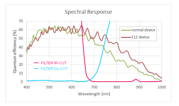
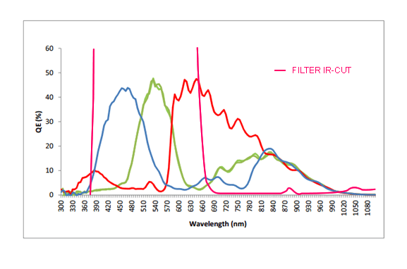
Color version
Gray scale version
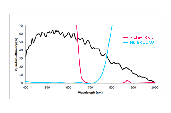
Gray scale version (-XD104a12)