Table of Contents
Introduction
The image acquisition chapter shows you the methods and processes behind an image acquisition as well as the two possibilities to acquire images:
-
single snap acquisition,
which means that the camera acquires a single image (see: Getting A Single Image). -
triggered acquisition,
which means that an external event initiates the image acquisition (see: Getting A Triggered Image)
With this newly acquired knowledge (the theory) you can see, by means of some examples, how the image acquisition works in practice.
Getting A Single Image
At least four steps are necessary to capture a single image from a Balluff device. These steps are explained with the help of source examples from ImpactControlCenter.
Step 1: The Device Needs To Be Initialized
Step 2: Request The Acquisition Of An Image
A live acquisition (running inside a thread function) could be implemented as follows:
- Note
- Images supplied to the user are locked for the driver. So if the user does not unlock the images, a permanent acquisition won't be possible as sooner or later all available requests will have been processed by the driver and have been returned to the user.
- See also
- Step 4.
Step 3: Wait Until The Image Has Been Captured
Step 4: Unlock The Image Buffer Once The Image Has Been Processed:
- Note
- ImpactControlCenter acquires images with the help of a capture thread. In order to avoid performance losses, the image buffer is locked during either the live or single image acquisition.
So after displaying the image the unlock is necessary!
Getting A Triggered Image
All trigger modes are defined by the enumeration
However, not every device will offer all these trigger modes but a subset of them. Valid trigger modes therefore can be found by reading the properties translation dictionary.
A sample on how to query a property's translation dictionary can be found here:
The Properties.cpp example application shows how to implement setting changes (like the trigger mode) with the C++ interface reference.
Cameras
All trigger modes are defined by the enumeration
The Properties.cpp example application shows how to implement setting changes (like the trigger mode) with the C++ interface reference.
For more specified information about triggered images with CCD sensors, please have a look at the "More specific data" link in the sensor tables.
Working With Settings
As already mentioned in the Quickstart chapter, settings contain all the parameters that are needed to prepare and program the device for the image capture. So for the user a setting is the one and only place where all the necessary modifications can be applied to achieve the desired form of data acquisition.
After a device has been initialized, the user will have access to a single setting named 'Base'. For most applications, this will be sufficient, as most applications just require the modification of a few parameters during start up and then at runtime these parameters stay constant.
This behavior can be achieved in two general ways:
- by settings the desired properties after the device has been initialized and before the image acquisition starts
- by setting up the device once interactively or with a small application and then store this parameter set and provide it as part of the application. During the device is initialized these set of parameters then can be used to set up the device
The first approach has the advantage, that no additional files are needed by the application, but modifying the acquisition parameters might force you recompile your code.
The second method typically results in a XML file containing all the parameters that can be shipped together with the application. The application in that case just calls a function to load a setting after the device has been initialized. Here parameters can be modified without the need to rebuild the application itself, but at least one additional file is needed and this file might be corrupted by unauthorized users leading the application to malfunction.
The function needed to load such a setting is mvIMPACT::acquire::FunctionInterface::loadSetting. A setting can be stored either by using one of the provided interactive GUI tools or by calling the function mvIMPACT::acquire::FunctionInterface::saveSetting
Working With More Than One Setting (device specific interface layout only)
- Note
- Features described in this section are available for the device specific interface layout only. See 'GenICam' vs. 'DeviceSpecific' Interface Layout for details.
Sometimes applications require the modification of parameters at runtime. This might become necessary e.g. when different regions of the image shall be captured at different times or when e.g. the exposure time must be adapted to the environment or for some other reason.
For the latter example, it's sufficient to acquire an image and use the image to determine the necessary exposure time for the next image from the acquired data and then set the expose time for the next acquisition and send a new image request to the device.
Modifying the AOI all the time might be tedious and sometimes it might be necessary to modify a large number of parameters back and forth. Here it would be more preferable to have two sets of parameters and tell the driver which setting to use for an acquisition when sending the request down to the driver.
To meet this requirement the Impact Acquire interface offers a method to create an arbitrary number of parameters.
A new setting can be created like this:
Settings Are Structured In Hierarchies
In order to allow the modification of certain parameters in an easy and natural way, settings are organized in a hierarchical structure. In default state (after a device has been initialized the first time or without stored new settings) every device offers just one setting called 'Base'.
Each new setting the user can create will be derived directly or indirectly from this setting. So after the user has created new settings like in the source sample from above these new parameter sets still depend on the 'Base' setting:
When now modifying a parameter in the setting 'Base' this will have direct impact on the new settings 'one' and 'two'. So this will provide a convenient way to change a parameter globally. Of course this is not always desired as then creating new settings wouldn't make any sense.
Modifying a parameter in one of the derived settings 'one' or 'two' will NOT influence the 'Base' or the other setting.
Furthermore modifying the same parameter in the 'Base' setting AFTER modifying the same parameter in one of the derived settings will NOT modify the derived setting anymore BUT will still modify in the setting that hasn't 'overwritten' the parameter:
- Note
- Assuming that 'Base' contains a property 'Gain_dB' with a value or 5.25:
- Note
- Now setting the property 'Gain_dB' in setting 'one' to a new value of 3.3 will result in this:
- Note
- Now setting the property 'Gain_dB' in setting 'Base' to a new value of 4.0 will result in this:
- Note
- Setting 'one' won't be affected as it has already overwritten the value.
However the original parent <-> child relationship can be restored by calling the corresponding restore to default method for the property in question:
Even the 'Base' setting has a default value for each property, that can be restored in the same way and affects all derived settings, that still refer to that original value :
Defining Which Setting To Use
When now the user has created all the parameter sets he needs for the application and has modified all the parameters to meet his requirements the only thing he needs to do afterwards to switch from one setting to another is to send the parameter set to use down to the device with the image request.
This can be done by modifying the property 'setting' in an image request control. An image request Control is an object that defines the behavior of the capture process. Each time an image is requested from the driver the user can pass the image request control to be used as a parameter of the request.
Chunk Data Format
In addition to the image data itself certain devices might be capable of sending additional information (e.g. the state of all the digital inputs and outputs at the time of the begin of the frame exposure) together with the image itself and some devices might even send NO image but only information for each captured frame. A typical scenario for the latter case would be some kind of smart device with a local application running on the device. It such a case a remote application could configure the device and the application and in order to minimize the amount of data to be captured/transmitted an application could decide only to send e.g. the result of a barcode decoding application. In such an application an image might be sent to the application only if the local application could not run successfully. For example if the local application is meant to detect barcodes but could succeed in doing so for some images the remote application might want to store the images where no barcode could be found for later analysis.
When a device is initialized the driver it will retrieve information about what additional information can be delivered by the device and will add these properties to the Info list of each request object.
Most devices will be capable of sending data in several formats, thus if NO additional information is configured for transmission, the features for accessing these information will be invisible and/or will not contain 'real' data. However when enabling the transmission of additional data, each request will contain up-to-date data for all the features that have been transmitted once the request object has been received correctly and has been returned to the application/the user.
When however a device does not support the transmission of additional chunk data or does support the transmission of a subset of the features published in this interface, then accessing any of the unsupported features without checking if the feature is available will either raise an exception (in object orientated programming languages) or will fail and report an error.
In order to distinguish between image data and additional information transmitted a certain buffer format is used. The device driver will then internally parse each buffer for additional information and will update the corresponding features in the request object of the Impact Acquire framework. The exact layout of the buffer format depends on the internal transfer technology used as well as on the interface design thus is not part of this documentation and therefore accessing the raw memory of a request by bypassing interface functions is not recommended and the result of doing so is undefined.
The most common additional features have been added to the interface. If a device offers additional features that can be transmitted but are not part of the current user interface these can still be obtained by an application by iterating over all the features in the Info list of the request object. How this can be done can e.g. be seen in the source code of ImpactControlCenter (look for occurrences of getInfoIterator) or have a look at the documentation of the function mvIMPACT::acquire::Request::getInfoIterator() to see a simple code snippet. Another more convenient approach for known custom features is to derive from mvIMPACT::acquire::RequestFactory (an example can be found there).
All features that are transmitted as chunk information will be attached to a sublist "Info/ChunkData" of a request object. The general concept of chunk data has been developed within GigE Vision and GenICam working groups. Detailed information about the layout of chunk data can be found in the GigEV Vision specification or in any other standard supporting the chunk data format. Detailed knowledge however is not important for accessing the data provided in chunk format as Impact Acquire does all the parsing and processing internally.
Multi-Part Format
Since version 2.20 Impact Acquire also supports the so called multi-part format that was developed mainly within GigE Vision and GenICam working groups. This format was triggered by the need to support 3D cameras and have an interoperable way to transfer 3D data which typically consists of several independent parts of data belonging together. So the main idea was to be able to report a single block of memory to the user that contains all this information and to have an interface that can access each part of this block of memory. A typical example where the multi-part format could be used is with a 3D camera or a dual head stereo camera where either multiple images that logically belong together (left sensor and right sensor or 3D image and confidence mask). But there are other use cases as well like e.g. when a device supports a hardware JPEG compressor an application might want to access both the raw data and the compressed data for different purposes like perform image processing on the raw data while streaming the compressed data via the network.
The API for accessing multi-part data belonging to a mvIMPACT::acquire::Request object basically consists of 2 functions:
When multi-part data is reported all the properties residing in the Image list of a request are don't care thus have the cfInvisible flag set. If normal (thus non-multi-part) data is reported all properties residing in the BufferParts list of a request are don't care thus have the cfInvisible flag set.
So the memory layout of a multi-part buffer can roughly be described like this:
One way of dealing with multi-part data in Impact Acquire could be implemented like this:
Limitations
Image Processing
Because of how Impact Acquire's internal image processing is currently implemented only the first part 2D buffer part encountered in a multi-part buffer can be processed by the host based Image Processing pipeline. All other buffer parts will be passed to the application as is. After at least one part has been processed and during this operation a new block of memory was allocated for the results the memory layout changes as it can be seen in the following diagram:
User Supplied Buffers
Because of how Impact Acquire's internal image processing is currently implemented providing an application allocated buffer (see mvIMPACT::acquire::FunctionInterface::imageRequestConfigure() for details) it is currently not possible to capture multi-part data into a user supplied buffer when at least one of the internal image processing functions that needs a destination buffer that is different from the source buffer is active. To find out whether a filter requires additional memory or not please refer to the corresponding Memory Consumption sections in the Image Processing chapter of this manual.
The reason for this limitation is that internally when a user supplied buffer is attached to a request this buffer will be attached at the output of the last filter in the internal processing chain that is active and requires a new buffer for the output data. So the user supplied buffer will serve as the 'Processed Buffer' from the last diagram in the previous section. All other parts belonging to an acquisition result will therefore NOT end up in the user supplied block of memory.
Acquiring Data
The image acquisition using Impact Acquire with Balluff hardware is handled driver-side by these queues:
- the request object queue
- the request queue
- the result queue
The main advantage of using queues is the independence of the capture process from side effects. Whenever the application and/or the operating system gets stuck as it is busy doing other things, in the background the driver can continue to work when it has image requests to process. Thus, short time intervals where the system doesn't schedule the applications threads can be buffered.
The following figure shows what the initial state of the driver's internal queues will look like when no request for an image has been made by the user:
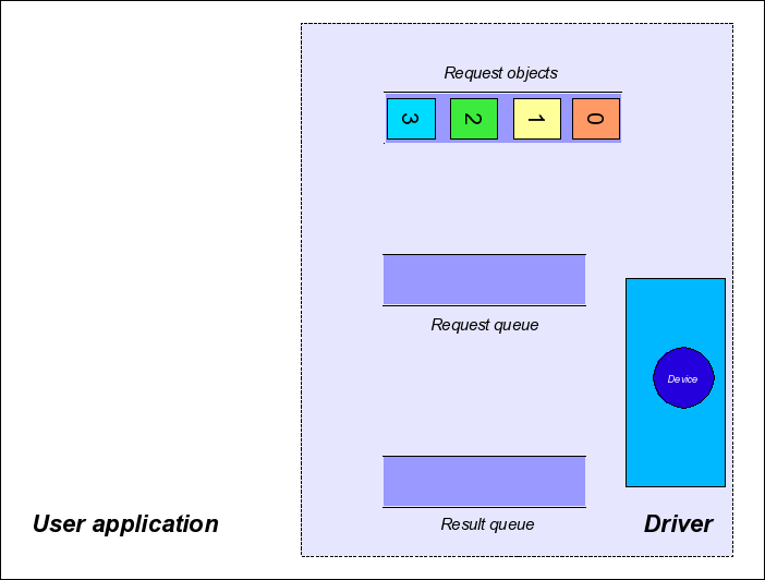
Within the user application, you can control the number of request objects with these functions:
The Capture Process
Step 1: Single Request
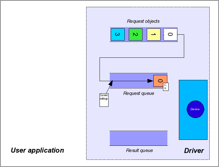
Whenever the user application requests an image, one of the request objects is placed in the request queue.
In device specific interface layout (see property InterfaceLayout of the device object or the enumeration mvIMPACT::acquire::Device::interfaceLayout for details) during this step all the settings (e.g. gain, exposure time, ...) that shall be used for this particular image request will get buffered, thus the driver framework will guarantee that these settings will be used to process this request.
In contrast to that when working with the GenICam interface layout, all modifications applied to settings will directly be written to the device thus in order to guarantee that a certain change is already reflected in the next image, the capture process must be stopped, then the changes must be applied and the capture process is restarted again.
- Note
- It is crucial to understand this fundamental difference between the two interface layouts! Please make sure you read the corresponding section of this manual: 'GenICam' vs. 'DeviceSpecific' Interface Layout
The function to send the request for one image down to the driver is named:
mvIMPACT::acquire::FunctionInterface::imageRequestSingle
- Note
- There is NO live mode. To implement a continuous capture it is recommended that the user application starts a thread that continuously requests images and returns the capture images or the result of an image processing back to the application.
- See also
- The ContinuousCapture example in the examples section of this documentation
Step 2: Image Capture
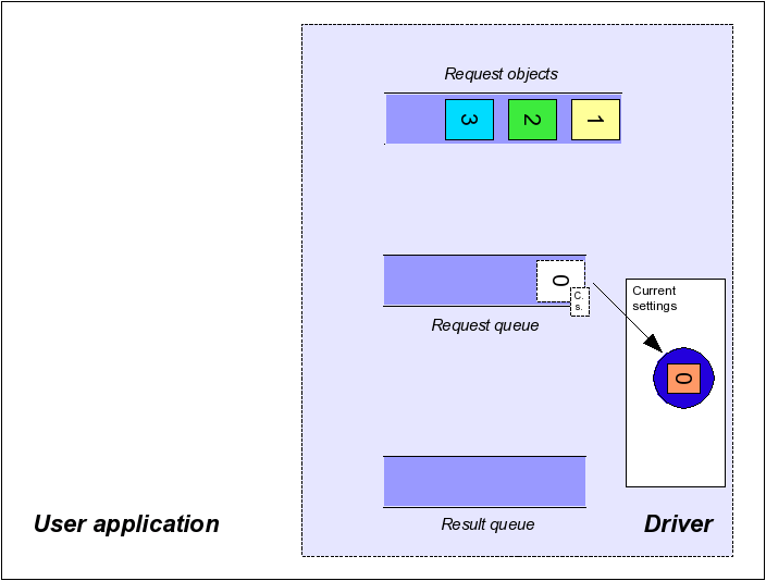
Whenever there are outstanding requests in the request queue the driver will always automatically remove the oldest request from this queue when it is either done processing the previous request OR was in idle mode. It will then try to capture data according to the desired capture parameters (such as gain, exposure time, etc.) into the buffer associated with this request.
Step 3: Result Queue
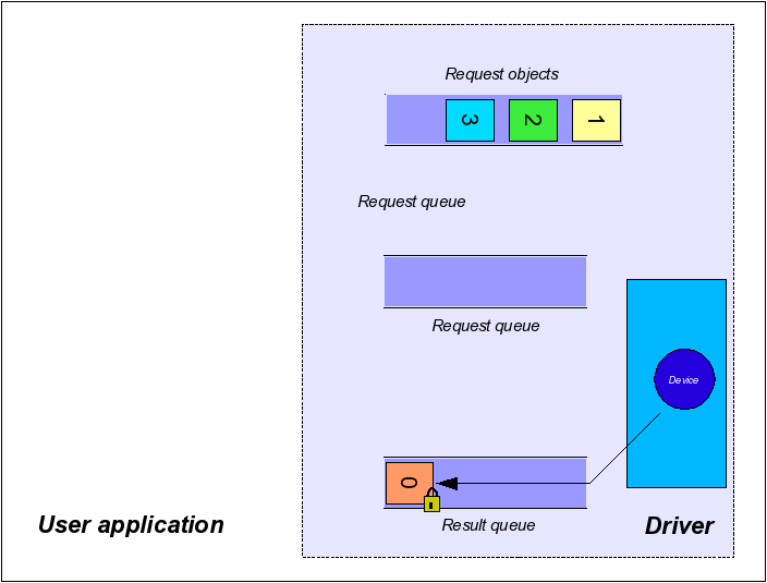
When the driver stops processing the current request object it locks the content (and therefore also the attached image) and thus guarantees not to change it until it is unlocked by the user again.
- Note
- The term 'stops processing' does NOT necessarily guarantee that an image has been captured. There might be error conditions that don't allow a complete image to be captured or timeout conditions that will stop processing the current request (see section 'Timeouts' later in this chapter. A buffer placed in the result queue can still be incomplete or corrupt. Each request object therefore has its very own Result property that carries additional information about the consistency of the buffer content that has been delivered.
Step 4: Request Wait For
When the user starts to wait for a request, the next available result queue entry will be returned to the application. The wait is a blocking function call. The function will return when either a request has been placed in the result queue by the driver or the user supplied timeout passed to the wait function call has elapsed. If there is at least one entry in the result queue already when the wait function is called, the function will return immediately. In order to check if there are entries in the result queue without waiting an application can pass 0 as the timeout value. However when the result queue is NOT empty, this call will remove one entry and return it to the application as would happen when passing a timeout value larger than 0, thus the application must always handle requests returned by the wait function. requests extracted from the result queue but NOT explicitly unlocked by the application will not be usable by the driver anymore!
This can be achieved by calling the function:
mvIMPACT::acquire::FunctionInterface::imageRequestWaitFor
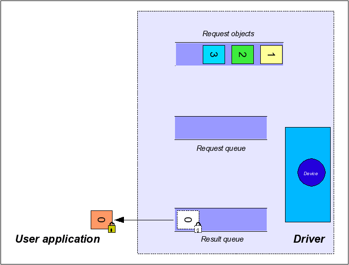
Step 5: Request Unlock
Request objects returned to the user are locked for the driver. So if the user does not unlock the images, the driver can't use this request object anymore and thus a permanent acquisition won't be possible as sooner or later all available requests will have been processed by the driver and have been returned to the user. Therefore, it is crucial to unlock request objects that have been processed by the user in order to allow the driver to use them again. This mechanism makes sure that the driver can't overwrite stuff the user still has to process and also makes sure that the user can't write into memory the driver will use to capture images into.
- Note
- Once unlocked the memory associated with the image is not guaranteed to remain valid, so it should not be accessed by the user application under any circumstances!
The functions to unlock the request buffer are called:
mvIMPACT::acquire::FunctionInterface::imageRequestUnlock
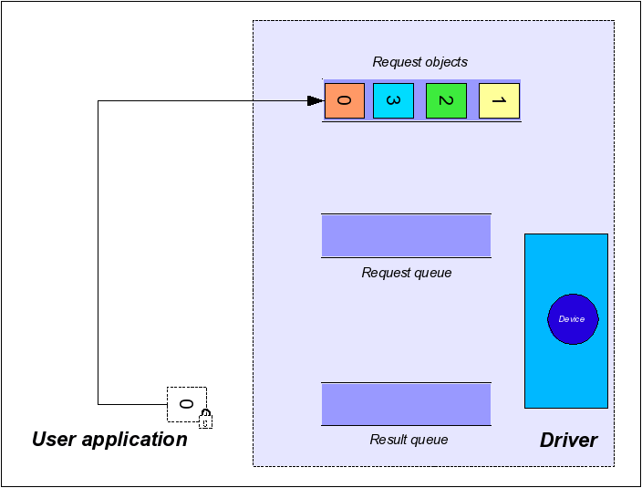
Reset The Queues
To restore the driver internal initial state (remove all queue entries from the chain of processing) this method can be used:
mvIMPACT::acquire::FunctionInterface::imageRequestReset
- Note
- Calling this function will NOT unlock requests currently locked by the user. A request object is locked for the driver whenever the corresponding wait function returns a valid request object. These objects must always be unlocked by the user explicitly.
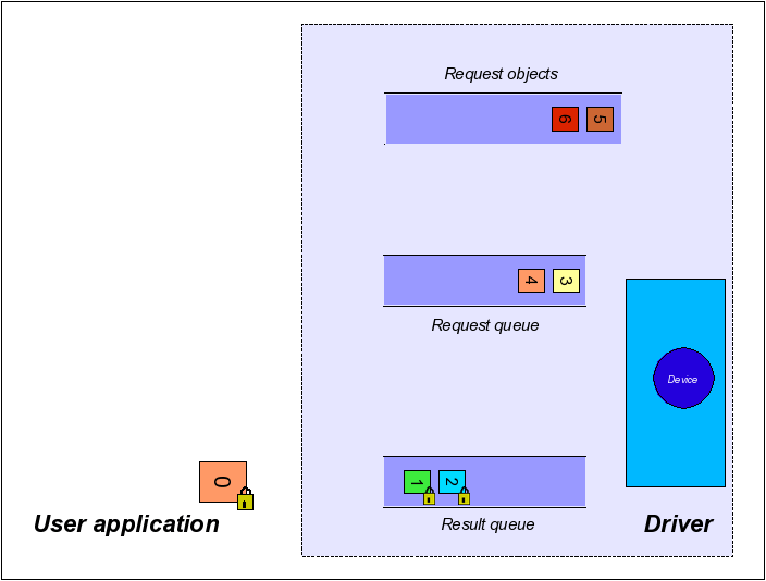
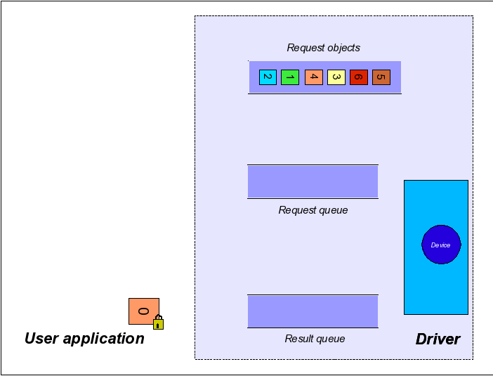
When not explicitly passing the request objects number to the driver when calling the imageRequestSingle function, the driver will use any of the request objects currently available to him, thus the order of the request objects might change randomly. An application should NOT rely on request objects arriving in a certain order unless explicitly stated by the application itself.
Timeouts
This section explains the different timeouts conditions that can occur during the capture process.
Two different timeouts have influence on the acquisition process. The first one is defined by the property ImageRequestTimeout_ms. This can be accessed like this:
mvIMPACT::acquire::BasicDeviceSettings::imageRequestTimeout_ms
This property defines the maximum time the driver tries to process a request. If this time elapses before e.g. an external trigger event occurred or an image was transmitted by the camera the request object will be returned to the driver. In that case, the driver will place this request object in the result queue and the user will get a valid request object when calling the corresponding 'wait for' function, but this request then will NOT contain a valid image, but it result property will contain mvIMPACT::acquire::rrTimeout.
- Note
- Since Impact Acquire 2.32.0 the default value for this property has been changed! See Calling 'imageRequestWaitFor' Never Returns / An Application No Longer Terminates After Upgrading To Impact Acquire 2.32.0 Or Greater for details.
The other timeout parameter is the timeout value passed to the 'wait for' function (described above). This value defines the maximum time in ms the function will wait for a valid image. After this timeout value elapsed, the function will return, but will not necessarily return a request object when no request object has been placed in the result queue.
Now assuming ImageRequestTimeout_ms is set to a value of 2000 ms the figure shows the status after, this is a triggered application and
- mvIMPACT::acquire::FunctionInterface::imageRequestSingle was called ONCE
Then the request queue will contain one entry:
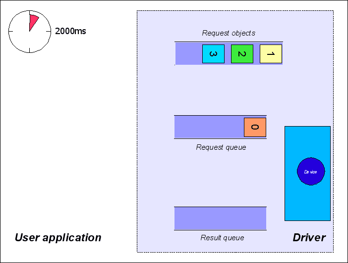
If now the next external trigger signal occurs AFTER the timeout of 2000ms has elapsed (or a trigger signal never occurs) the driver will place the unprocessed request object in its result queue.
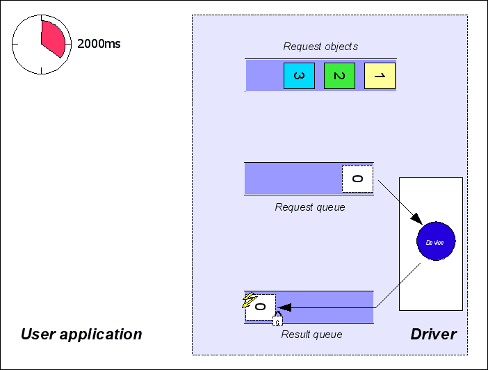
From here, it will be returned to the user immediately the next time mvIMPACT::acquire::FunctionInterface::imageRequestWaitFor is called. mvIMPACT::acquire::Request::requestResult will contain mvIMPACT::acquire::rrTimeout (figure 11) now
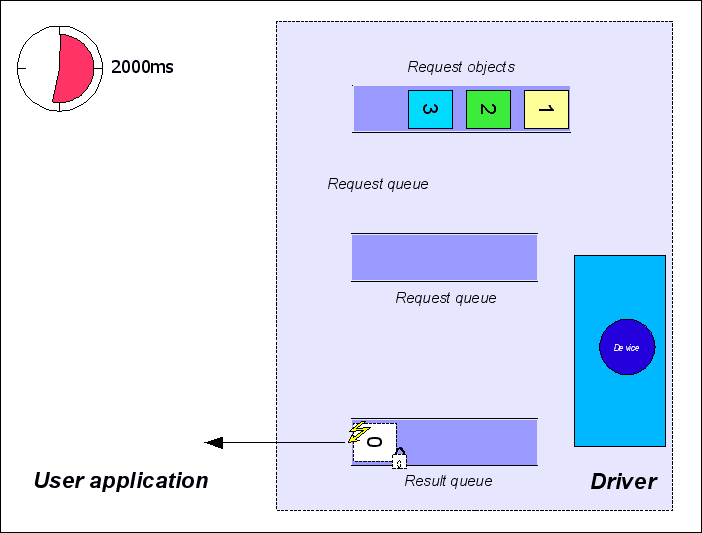
- Note
- If no further call to mvIMPACT::acquire::FunctionInterface::imageRequestSingle has been made, the next triggered image will be lost, as the driver will silently discard the trigger signal because he has no request to process.
If the next external trigger comes BEFORE the timeout of 2000ms has elapsed, an image will be captured and the next call to mvIMPACT::acquire::FunctionInterface::imageRequestWaitFor will return after the image is ready, passing a valid image back to the user. mvIMPACT::acquire::Request::requestResult will contain mvIMPACT::acquire::rrOK.
- Note
- All requests returned by mvIMPACT::acquire::FunctionInterface::imageRequestWaitFor need to be unlocked in ANY case independent from mvIMPACT::acquire::Request::requestResult.
It's important to realize that even several calls to
mvIMPACT::acquire::FunctionInterface::imageRequestWaitFor are possible to wait for a single request object. Until no image has been placed in the result queue each call will return after its timeout has elapsed returning mvIMPACT::acquire::DEV_WAIT_FOR_REQUEST_FAILED . However, waiting multiple times for an image has NO effect on the position of the request objects in their queues. This is only when either an image has been captured or when the timeout defined by the property ImageRequestTimeout_ms has elapsed.
Acquisition Start/Stop Behaviour
A couple of other features need to be mentioned when explaining Impact Acquire's buffer handling and data acquisition behaviour:
- the functions mvIMPACT::acquire::FunctionInterface::acquisitionStart and mvIMPACT::acquire::FunctionInterface::acquisitionStop
- the property mvIMPACT::acquire::Device::acquisitionStartStopBehaviour
- the property mvIMPACT::acquire::SystemSettings::acquisitionIdleTimeMax_ms
Some devices (e.g. GigE Vision devices) use a streaming approach to send data to the host system. This means once started the device will send its data to the host system as it becomes ready and does NOT wait for the host system to ask for data (such as an image). For the host system that can result in data being lost if it does not provide a sufficient amount of buffers to acquire the data into. Thus whenever a device is generating images, frames or data buffers faster than the host system can provide capture buffers, data is lost.
Some device/driver combinations therefore support 2 different ways to control the start/stop behaviour of data streaming from a device:
- An automatic mode where the device driver internally decides when to start and when to stop the device's streaming channel. In this mode the driver will automatically send a 'start streaming' command to the device once the first request command is issued using the mvIMPACT::acquire::FunctionInterface::imageRequestSingle function. When the request queue runs empty the driver will wait the amount of milliseconds defined by the
AcquisitionIdleTimeMax_msproperties. If no new request command is issued during that time, the driver will automatically send a 'stop streaming' command to the device - A user controlled mode where the application must explicitly start and stop the data transmission from the device to the host system
While the automatic mode keeps the application code fairly simple, the user controlled mode will sometimes allow a much better control about the capture process. Especially for applications where NO data loss can be accepted, the user controlled mode might be the better choice even though it requires a bit of additional code on the application side.
If the user controlled mode is supported the AcquisitionStartStopBehaviour property's translation dictionary will contain the assbUser value. The default mode will be assbDefault, but if supported an application can switch to assbUser BEFORE the device is opened.
- Note
- Some devices (e.g. all devices belonging to mvBlueLYNX-X family) will ONLY support the application controlled mode. For the mvBlueLYNX-X this also comes with another restriction: All buffers that will be used to capture data into between a call to the acquisition start function and the acquisition stop function must be announced to the driver by calling the function mvIMPACT::acquire::FunctionInterface::imageRequestSingle BEFORE starting the acquisition thus when there are 6 request objects all these 6 objects should be announced and then the acquisition should be started. This is for performance reasons. Buffers announced after calling the acquisition start command will be rejected by the driver!
-
The property
AcquisitionStartStopBehaviourwill become read-only after the device has been opened.
Situations where an application controlled start and stop of the device's data transmission might be beneficial:
- NO loss of data can be tolerated
- an application runs at very high frame rates (Otherwise especially when requesting the first buffer data might be lost, as when internally starting the data streaming from device the request queue might immediately run empty again (there is just a single buffer at that moment) as the device might send frames faster than additional buffers get queued by the application)
When the application controls the start and stop of the streaming from the device some additional code must be added to an application:
