Loading...
Searching...
No Matches
Using external trigger with CMOS sensors
Scenario
The CMOS sensors used in BVS CA-MLC/-IGC cameras support the following trigger modes:
ContinuousOnDemand(software trigger)OnLowLevelOnHighLevelOnHighExpose(only with some sensors)
If an external trigger signal occurs (e.g. high), the sensor will start to expose and readout one image. Now, if the trigger signal is still high, the sensor will start to expose and readout the next image (see Figure 1, upper part). This will lead to an acquisition just like using continuous trigger.
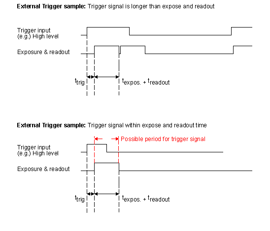
- ttrig = Time from trigger (internal or external) to integration start.
If you want to avoid this effect, you have to adjust the trigger signal. As you can see in Figure 1 (lower part), the possible period has to be smaller than the time an image will need (texpose + treadout).
Example
External synchronized image acquisition (high active)
- Note
- Using BVS CA-MLC or BVS CA-IGC, you have to select DigIn0 as the trigger source, because the camera has only one opto-coupled input. Only the TTL model of the BVS CA-MLC has two I/O's.
- Trigger modes
OnHighLevel:
The high level of the trigger has to be shorter than the frame time. In this case, the sensor will make one image exactly. If the high time is longer, there will be images with the possible frequency of the sensor as long as the high level takes. The first image will start with the low-high edge of the signal. The integration time of the exposure register will be used.OnLowLevel:
The first image will start with the high-low edge of the signal.OnHighExpose
This mode is likeOnHighLevel, however, the exposure time is used like the high time of the signal.
- See also
- Block diagrams with example circuits of the opto-isolated digital inputs and outputs can be found in Technical Data.