Introduction
The CMOS sensor module (MT9V034) incorporates the following features:
- resolution to 752 x 480 gray scale or RGB Bayer mosaic
- supports window AOI mode with faster readout
- high dynamic range 110 dB
- programmable analog gain (0..12 dB)
- progressive scan sensor (no interlaced problems!)
- full frame shutter
- programmable readout timing with free capture windows and partial scan
- many trigger modes (free-running, hardware-triggered)
Details of operation
The sensor uses a full frame shutter (ShutterMode = "FrameShutter"), i.e. all pixels are reset at the same time and the exposure commences. It ends with the charge transfer of the voltage sampling.
Furthermore, the sensor offers two different modes of operation:
- free running mode (Overlapping exposure and readout)
- snapshot mode (Sequential exposure and readout)
Free running mode
In free running mode, the sensor reaches its maximum frame rate. This is done by overlapping erase, exposure and readout phase. The sensor timing in free running mode is fixed, so there is no control when to start an acquisition. This mode is used with trigger mode Continuous.
To calculate the maximum frames per second (FPSmax) in free running mode you will need following formula:
FrameTime = (ImageWidth + 61) * ((ImageHeight + 45) / PixelClock)
If exposure time is lower than frame time:
FPS_max =            1
           ----------------------
                 FrameTime
If exposure time is greater than frame time:
FPS_max =            1
           ----------------------
                ExposureTime
Snapshot mode
In snapshot mode, the image acquisition process consists off several sequential phases:
Trigger
Snapshot mode starts with a trigger. This can be either a hardware or a software signal.
The following trigger modes are available:
| Mode | Description |
| Continuous | Free running, no external trigger signal needed. |
| OnDemand | Image acquisition triggered by command (software trigger). |
| OnLowLevel | As long as trigger signal is Low camera acquires images with own timing. |
| OnHighLevel | As long as trigger signal is High camera acquires images with own timing. |
Erase, exposure and readout
All pixels are light sensitive at the same period of time. The whole pixel core is reset simultaneously and after the exposure time all pixel values are sampled together on the storage node inside each pixel. The pixel core is read out line-by-line after exposure.
- Note
- Exposure and read out cycle is carry-out in serial; that causes that no exposure is possible during read out.
The step width for the exposure time is 1 us.
Image data is then shifted out line-by-line and transferred to memory.
To calculate the maximum frames per second (FPSmax) in snapshot mode you will need following formula:
FrameTime = (ImageWidth + 61) * ((ImageHeight + 45) / PixelClock)
FPS_max =                  1
           -----------------------------------
                 FrameTime + ExposureTime
Measured frame rates
| AOI | PixelClock (MHz) | Exposure Time (us) | Maximal Frame Rate (fps) | PixelFormat |
| Maximum | 40 | 100 | 93.7 | Mono8 |
| W:608 x H:388 | 40 | 100 | 131.4 | Mono8 |
| W:492 x H:314 | 40 | 100 | 158.5 | Mono8 |
| W:398 x H:206 | 40 | 100 | 226.7 | Mono8 |
Sensor Data
Device Structure
- Progressive scan CMOS image sensor
- Image size: 4.51(H)x2.88(V)mm (Type 1/3")
- Number of effective pixels: 752 (H) x 480 (V)
- Unit cell size: 6um (H) x 6um (V)
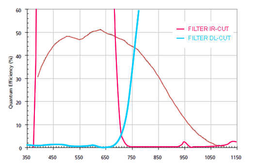
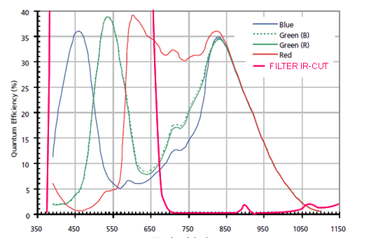
Characteristics
Color version
Gray scale version