General
Impact Acquire has a broad spectrum of image processing filters at its' disposal, to ensure that the resulting processed image meets the requirements for even the most demanding application. These filters range from rudimentary filters which are often absolutely necessary (e.g. de-bayering) to filters which provide convenience (e.g. mirror) and optimization functionalities (e.g. flat-field correction).
Most of these filters will be applied on the host, thus will introduce additional CPU load when enabled. However these filters use highly optimized algorithms that try to run as fast as possible on a given machine. Not every filter is supported on every operating system.
The following list is a comprehensive table containing every filter and its availability on each operating system:
| Windows® | Linux x86_64 | Linux ARMhf | Linux ARM64 | ||
|---|---|---|---|---|---|
| Format Reinterpreter | ✓ | ✓ | ✓ | ✓ | |
| Defective Pixels | ✓ | ✓ | ✓ | ✓ | |
| Dark Current | ✓ | ✓ | ✓ | ✓ | |
| Flat Field | ✓ | ✓ | ✓ | ✓ | |
| Tap Sort | ✓ | ✓ | ✓ | ✓ | |
| Gain Offset Knee | Gain | ✓ | ✓ | ||
| Offset | ✓ | ✓ | ✓ | ✓ | |
| Knee | ✓ | ✓ | ✓ | ✓ | |
| Polarized Data Extraction | ✓ | ✓ | ✓ | ✓ | |
| PolarizedDataExtractionMode = PseudoColorRepresentation | ✓ | ✓ | |||
| Mirror | ✓ | ✓ | ✓ | ✓ | |
| Bayer | ✓ | ✓ | ✓ | ✓ | |
| Sharpen | ✓ | ✓ | ✓ | ✓ | |
| Saturation | ✓ | ✓ | ✓ | ✓ | |
| Color Twist | 2.2.2 | 2.2.2 | 2.40.0 | 2.40.0 | |
| LUT | Threshold | ✓ | ✓ | ✓ | ✓ |
| Linear Interpolation | ✓ | ✓ | |||
| Cubic Interpolation | ✓ | ✓ | |||
| Soft-Scaler | ✓ | ✓ | |||
| Channel Split | ✓ | ✓ | ✓ | ✓ | |
| Watermark | ✓ | ✓ | |||
| Rotation | ✓ | ✓ | |||
| Format Conversion | ✓ | ✓ | ✓ | ✓ | |
- Note
- Some of the filters will require additional RAM when enabled. The amount of RAM needed by each filter is documented in the individual sections for each filter further down in this chapter. The way the memory is allocated in general can be influenced by an application by writing to the mvIMPACT::acquire::SystemSettings::imageProcessingOptimization
Depending on the value of this property the memory consumption can either be larger but static (thus less heap fragmentation will occur) or low but dynamic resulting in a smaller memory footprint but a higher risk of heap fragmentation. Depending on the application this property can have a massive influence on the overall system stability and performance. When configured to use a smaller memory footprint(this is the default for backward compatibility) e.g. when doing debayering on the host system the overall memory consumption will not increase significantly but as buffers are allocated as needed and freed as fast as possible after time the heap memory might get fragmented until no more buffers of the needed size can be allocated causing the application to stop functioning. This is especially true when the application itself works with the heap a lot and uses lots of small blocks. In such a scenario it might therefore be beneficial to use a more static heap usage approach. This has the drawback, that the overall memory consumption of the process will increase by a certain amount depending on various parameters:
- the number of devices operated in parallel
- the amount of requests buffers allocated for each device
- the size of the individual request buffers
- the number of enabled filters per device (host debayering, scaler, etc.)
If this is acceptable the static heap approach will result in a more robust application.
The Image Processing filters of Impact Acquire are chained in a strict order, which is also reflected by the order of properties in ImpactControlCenter that cannot be changed and is depicted in the following figure:
Image Processing Mode
From the picture above it can be seen that an image can take several ways through the image processing pipeline! Depending of the property mvIMPACT::acquire::SystemSettings::imageProcessingMode an application can influence whether an image shall be processed or not. Sometimes this can be useful e.g. if a viewer application applies a lot of processing to the image data on the host and therefore the host system is not capable of processing every image delivered by the device in the current configuration. When now both the result of the processing as well as the full theoretical frame rate are of interest but it is not important that every image gets processed and displayed, the framework can be configured in a way that only some of the images get processed while others will only be acquired but will be returned without processing to the user. This can be done by decoupling the image processing from the acquisition engine. As something like this requires the use of at least one additional thread per device driver instance this will not be done by default, but must be enabled explicitly by an application by setting the property mvIMPACT::acquire::Device::userControlledImageProcessingEnable to true BEFORE the device is initialised. If this is done additional properties will become available under SystemSettings/ImageProcessing. The most important one will be the ImageProcessingMode just mentioned. It can be used to influence the behaviour of the image processing pipeline. Without setting this property to true (which is the default behaviour) the image processing on the host will be done in the thread context of the acquisition engine.
Multithreading
Impact Acquire internally makes massive use of various techniques to improve the overall processing performance. One of these techniques is OpenMP (https://en.wikipedia.org/wiki/OpenMP) for distributing the load caused by the image processing algorithms described by this chapter. Usually the OpenMP runtime chooses acceptable default parameters for these tasks but sometimes or on some platforms manual adjustment might become necessary.
Depending on the compiler used to build Impact Acquire and the version of the OpenMP specification implemented by this compiler it is either possible to define a maximum thread count for each individual device driver instance (Linux) or a fixed value used by the whole process an application is running in (Windows®). In the latter case Impact Acquire will not offer any API function to configure the thread count. Instead this can either be achieved by setting the environment variable OMP_NUM_THREADS before using any OpenMP features or by calling the function omp_set_num_threads anywhere in the code. The maximum size of the thread pool will adjust afterwards. The runtime might still decide to use less threads but never more!
In case a newer version of the OpenMP specification was supported by the compiler Impact Acquire will offer the property
This property can be used to adjust the maximum number of threads that will be used for image processing by THIS DEVICE DRIVER INSTANCE. To see the effect of increasing the number of threads please have a look at the following screenshot made with ImpactControlCenter:
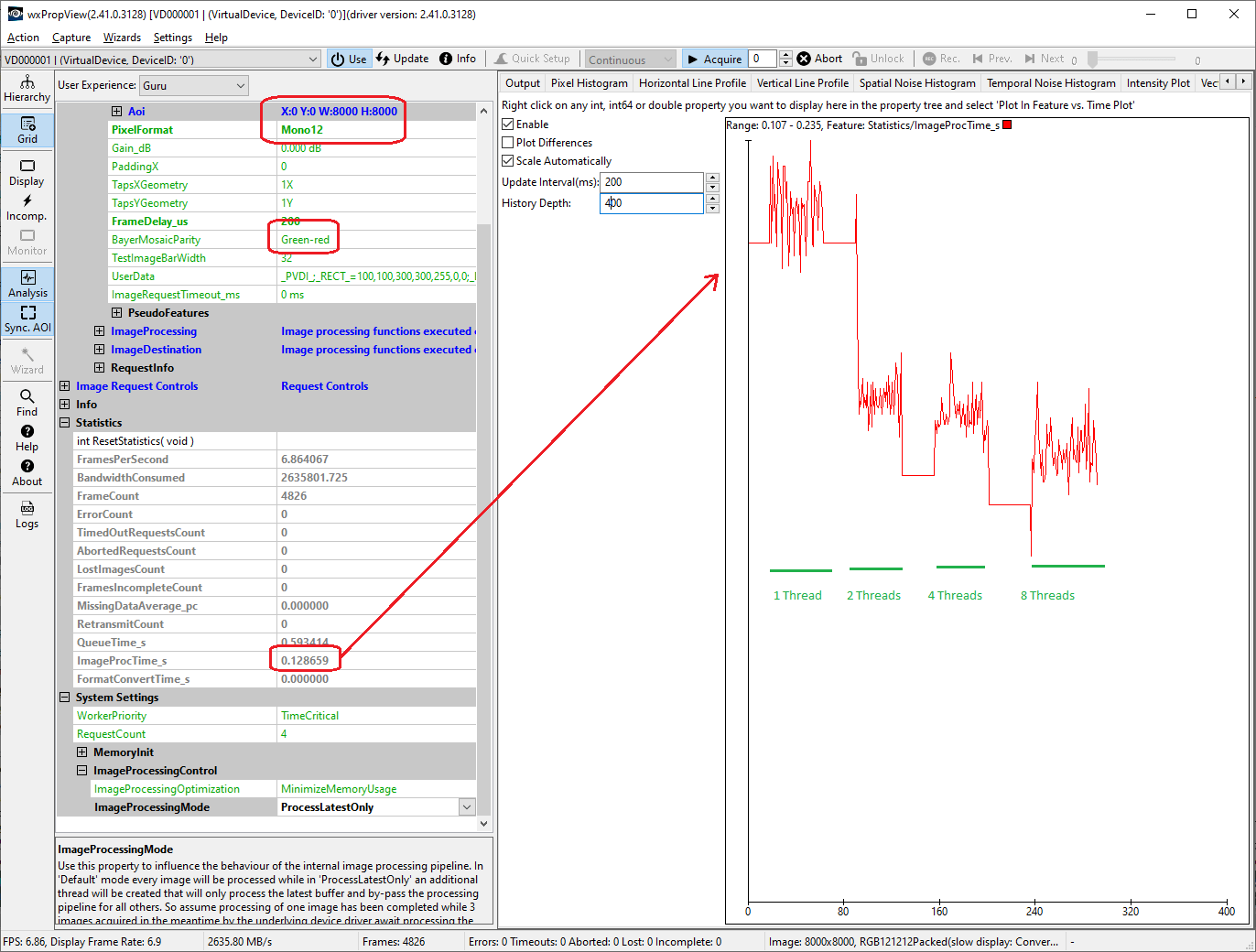
This picture was taken on a systems with 8 CPUs (4 physical cores with Hyper-Threading enabled). It can be seen that the performance gain is getting smaller and smaller when adding more threads. The total CPU load however increases proportionally, so even if the speed gain between 4 and 8 CPUs is just about 10-15 percent the CPU load will almost double. It therefore is not always wise to set this value to the maximum. A library supporting the feature will initialize this value to half the number of CPUs.
Pixel Formats Supported By The Individual Filters
- Note
- Not all devices support all filters! Also not every filter will be available on every platform!
Every filter in the above chain has different properties and different requirements. For example, it is obvious that the Bayer, sharpen and saturation filter, which is responsible for debayering mosaics, will not be able to accept already debayered pixel formats as input, but its output will most probably be a de-Bayered pixel format.
The following list is a comprehensive table with the pixel formats accepted and produced by all Image Processing filters of Impact Acquire:
| Format Reinterpreter | Defective Pixels | Dark Current | Flat Field | Tap Sort | Gain Offset Knee | Polarized Data Extraction | Mirror | Bayer | Sharpen | Saturation | Color Twist | LUT | Soft-Scaler | Channel Split | Watermark | Rotation | Format Conversion | |||||
|---|---|---|---|---|---|---|---|---|---|---|---|---|---|---|---|---|---|---|---|---|---|---|
| in | out | in/out | in/out | in/out | in/out | in/out | in | out | in/out | in | out | in/out | in/out | in/out | in/out | in/out | in | out | in/out | in/out | in/out | |
| Mono8 | 2.10.1 | 1.4.0 | 1.4.0 | 1.4.0 | 1.10.7 | 1.10.97 | 2.29.0 | 2.29.0 | 1.2.1 | 1.1.1 | 1.1.1 | 1.2.0 | 1.12.0 | 1.10.71 | 1.10.31 | 1.11.18 | 1.11.18 | 1.10.97 | 1.10.31 | 1.1.1 | ||
| Mono10 | 2.10.1 | 1.4.0 | 1.4.0 | 1.4.0 | 1.10.7 | 1.10.97 | 2.29.0 | 2.29.0 | 1.2.1 | 1.10.64 | 1.12.0 | 1.10.71 | 1.10.31 | 1.11.18 | 1.11.18 | 1.10.97 | 1.10.31 | 1.1.1 | ||||
| Mono12 | 2.10.1 | 1.4.0 | 1.4.0 | 1.4.0 | 1.10.7 | 1.10.97 | 2.29.0 | 2.29.0 | 1.2.1 | 1.10.64 | 1.12.0 | 1.10.71 | 1.10.31 | 1.11.18 | 1.11.18 | 1.10.97 | 1.10.31 | 1.1.1 | ||||
| Mono12Packed_v1 | 2.5.0 | 2.5.0 | 2.5.0 | 2.5.0 | 2.5.0 | |||||||||||||||||
| Mono12Packed_v2 | 1.11.41 | 1.12.39 | 1.11.18 | 1.11.18 | 1.11.0 | |||||||||||||||||
| Mono14 | 2.10.1 | 1.4.0 | 1.4.0 | 1.4.0 | 1.10.7 | 1.10.97 | 2.29.0 | 2.29.0 | 1.2.1 | 1.10.64 | 1.12.0 | 1.10.71 | 1.10.31 | 1.11.18 | 1.11.18 | 1.10.97 | 1.10.31 | 1.1.1 | ||||
| Mono16 | 2.10.1 | 1.4.0 | 1.4.0 | 1.4.0 | 1.10.7 | 1.10.97 | 2.29.0 | 2.29.0 | 1.2.1 | 1.10.64 | 1.12.0 | 1.10.71 | 1.10.31 | 1.11.18 | 1.11.18 | 1.10.97 | 1.10.31 | 1.10.31 | ||||
| BGR888Packed | 2.10.1 | 2.33.0 | 1.11.20 | 1.11.20 | 1.1.1 | 1.11.20 | 1.11.20 | 1.11.20 | 1.11.20 | 1.11.20 | 1.11.20 | 1.11.20 | ||||||||||
| BGR101010Packed_v2 | 1.11.42 | 1.11.42 | ||||||||||||||||||||
| RGB888Packed | 2.10.1 | 2.33.0 | 1.10.97 | 1.2.1 | 1.6.5 | 1.6.5 | 1.10.71 | 1.10.92 | 1.11.18 | 1.10.97 | 1.10.31 | 1.10.31 | ||||||||||
| RGB101010Packed | 2.10.1 | 2.33.0 | 1.10.97 | 1.10.92 | 1.9.3 | 1.9.3 | 1.10.71 | 1.10.92 | 1.11.18 | 1.10.97 | 1.10.92 | 1.10.31 | ||||||||||
| RGB121212Packed | 2.10.1 | 2.33.0 | 1.10.97 | 1.10.92 | 1.9.3 | 1.9.3 | 1.10.71 | 1.10.92 | 1.11.18 | 1.10.97 | 1.10.92 | 1.10.31 | ||||||||||
| RGB141414Packed | 2.10.1 | 2.33.0 | 1.10.97 | 1.10.92 | 1.9.3 | 1.9.3 | 1.10.71 | 1.10.92 | 1.11.18 | 1.10.97 | 1.10.92 | 1.10.31 | ||||||||||
| RGB161616Packed | 2.10.1 | 2.33.0 | 1.10.97 | 1.10.92 | 1.9.3 | 1.9.3 | 1.10.71 | 1.10.92 | 1.11.18 | 1.10.97 | 1.10.92 | 1.10.31 | ||||||||||
| RGBx888Packed | 2.33.0 | 1.10.97 | 1.10.20 | 1.2.0 | 1.2.0 | 1.12.0 | 1.10.71 | 1.11.20 | 1.11.18 | 1.11.20 | 1.10.31 | 1.10.31 | ||||||||||
| RGB888Planar | 2.17.0 | 2.38.0a | 2.17.0 | 2.17.0 | 2.17.0 | 2.17.0 | 2.17.0 | 2.17.0 | 2.17.0 | |||||||||||||
| RGBx888Planar | 1.11.8 | 1.8.4 | 1.12.39 | 1.7.5 | 1.11.18 | 1.11.20 | 1.11.42 | 1.10.31 | ||||||||||||||
| YUV411_UYYVYY_Packed | 2.13.0 | 2.13.0 | 2.13.0 | |||||||||||||||||||
| YUV422Packed | 1.11.8 | 1.11.8 | 1.2.0 | 1.5.0 | 1.7.5 | 1.11.18 | 1.10.97 | 1.10.31 | ||||||||||||||
| YUV422Planar | 1.11.8 | 1.8.4 | 1.11.18 | 1.10.97 | 1.10.31 | |||||||||||||||||
| YUV422_10Packed | 1.11.8 | 1.10.92 | 1.11.18 | 1.11.8 | 1.11.8 | |||||||||||||||||
| YUV422_UYVYPacked | 1.11.8 | 1.10.8 | 1.10.92 | 1.11.18 | 1.10.97 | 1.10.92 | ||||||||||||||||
| YUV422_UYVY_10Packed | 1.11.42 | 1.10.42 | 1.11.18 | 1.11.8 | 1.11.8 | |||||||||||||||||
| YUV444_UYVPacked | 2.33.0 | 1.11.42 | 1.10.42 | 1.11.42 | 1.11.42 | 1.11.42 | 1.11.42 | 1.11.42 | 1.11.42 | |||||||||||||
| YUV444_UYV_10Packed | 2.33.0 | 1.11.42 | 1.10.42 | 1.11.42 | 1.11.42 | 1.11.42 | 1.11.42 | 1.11.42 | 1.11.42 | |||||||||||||
| YUV444Packed | 2.33.0 | 1.11.42 | 1.10.42 | 1.11.42 | 1.11.42 | 1.11.42 | 1.11.42 | 1.11.42 | 1.11.42 | |||||||||||||
| YUV444_10Packed | 2.33.0 | 1.11.42 | 1.10.42 | 1.11.42 | 1.11.42 | 1.11.42 | 1.11.42 | 1.11.42 | 1.11.42 | |||||||||||||
aThe output pixel format if PolarizedDataExtractionMode is set to PseudoColorRepresentation
- Note
- The version numbers in the table represent the Impact Acquire version where initial support has been added for a certain filter/format combination.
In case a pixel format is selected to be processed with a filter which does not support this particular pixel format, an appropriate error message will be logged. Please note that Bayer pixel formats are handled like Mono formats with the same bit-depth.
For more information about each individual filter you may refer to the section below.
Pixel Formats in Impact Acquire and Other Contexts
In contrast to image file formats, pixel format names differ between contexts where they are used. As an example, in the Windows® RGB bitmaps, the B color part comes first, then the G part and then the R part, which makes it a BGR pixel format in the Pixel Format Naming Convention which is widely used in the GenICam™ standard as well as in camera standards like the GigE Vision™ and the USB3 Vision™ standard.
On the other hand, the term pixel format generally refers to the format and layout of single pixels, but is also used to describe the layout of whole image formats. In this respect its meaning depends on the domain where it is used.
- In the Pixel Format Naming Convention(PFNC), there are mostly pixel-based format names and extensions for image formats that can be described in a similar way, like planar images.
- In Video For Linux, pixel formats usually describe the layout of single pixels as well as the overall image format are usually (see the corresponding chapter in the Video For Linux documentation).
Since Impact Acquire needs unique names for pixel formats across domains, they may differ from the names in certain domains.
- Many Impact Acquire pixel format names were chosen when Windows® was the main platform, which explains why most Impact Acquire RGB* formats are called BGR* in other domains and vice versa.
- Many Impact Acquire pixel format names were created when GigE Vision™ was developed, where many pixel format names had a trailing Packed in case they were stored in less than full 2n bytes.
- The widely accepted term YUV naming was used although technically speaking, we always deal with YCbCr. Doubling names would have created inconsistancies or incompatibilities in the future.
For clarification, the following table contains the "translation" from Impact Acquire pixel format names to names in the Pixel Format Naming Convention(PFNC) and in Video For Linux(V4L2).
| Impact Acquire name | PFNC name | V4L2 enum |
|---|---|---|
| Mono8 | Mono8 | V4L2_PIX_FMT_GREY |
| Mono10 | Mono10 | V4L2_PIX_FMT_Y10 |
| Mono12 | Mono12 | V4L2_PIX_FMT_Y12 |
| Mono12Packed_v1 | Mono12p | - |
| Mono12Packed_v2 | Mono12Packeda | - |
| Mono14 | Mono14 | V4L2_PIX_FMT_Y14 |
| Mono16 | Mono16 | V4L2_PIX_FMT_Y16 |
| Mono32 | Mono32 | - |
| BGR888Packed | RGB8 | V4L2_PIX_FMT_RGB24 |
| BGR101010Packed_v2 | RGB10p32 | - |
| RGB888Packed | BGR8 | V4L2_PIX_FMT_BGR24 |
| RGB101010Packed | BGR10 | - |
| RGB121212Packed | BGR12 | - |
| RGB141414Packed | BGR14 | - |
| RGB161616Packed | BGR16 | - |
| RGBx888Packed | BGRa8 | V4L2_PIX_FMT_BGRA32 |
| RGB888Planar | RGB8_Planar | - |
| RGBx888Planar | RGBa8_Planar | - |
| YUV411_UYYVYY_Packed | YUV411_8_UYYVYY | - |
| YUV422Packed | YUV422_8 | V4L2_PIX_FMT_YUYV |
| YUV422Planar | YUV422_8_YVU_Planar | - |
| YUV422_10Packed | YUV422_10 | V4L2_PIX_FMT_Y210 |
| YUV422_UYVYPacked | YUV422_8_UYV | V4L2_PIX_FMT_UYVY |
| YUV422_UYVY_10Packed | YUV422_10_UYV | - |
| YUV444_UYVPacked | YUV8_UYV | - |
| YUV444_UYV_10Packed | YUV10_UYV | - |
| YUV444Packed | YUV8 | V4L2_PIX_FMT_YUV24 |
| YUV444_10Packed | YUV10 | - |
| YUV444Planar | YUV444_8_YVU_Planar | - |
aA non-PFNC format defined in GigE Vision™ 1.x
Individual Filters
Format Reinterpreter Filter
E.g. some CameraLink cameras transmit data in a non standard compliant way. E.g. some cameras use the 1X8 mono mode but effectively transmit RGB data. This filter can be used to treat such a format in a way that it can be post-processed and displayed correctly. This is done by modifying the parameters describing the buffer and NOT by modifying the actual pixel data itself. For example if a device sends out RGB data but transmits it using a mono format described by a certain standard, after passing this filter the mono buffer will have a width that became divided by 3 while preserving the original pitch and now the buffer will have 3 channels instead. This will allow correct post-processing and displaying of the data.
In addition to that by using the MonoX_To_MonoX modes an application can modify the Bayer mosaic parity attribute of a buffer. It is possible to either attach a parity to a mono buffer, remove the current attribute or change the current one.
All filters applied AFTER this filter will see the changed attributes thus treat this buffer as defined by the output format of the filter.
The following properties can be used to configure this filter:
- mvIMPACT::acquire::ImageProcessing::formatReinterpreterEnable
- mvIMPACT::acquire::ImageProcessing::formatReinterpreterMode
- mvIMPACT::acquire::ImageProcessing::formatReinterpreterBayerMosaicParity
Memory Consumption
This filter does require NO additional memory.
Defective Pixels Filter
Due to manufacturing imperfections of the sensors, some pixels may turn out to be defective. They may either be brighter than they should (leaky pixels, detectable in dark images) or they may be darker than expected (cold pixels, detectable in bright images). The Defective Pixel Correction filter replaces those faulty pixels with either the average or the median of the surrounding pixels, depending on the replacement method chosen by the user. The Defective Pixel Correction filter is a pixel-wise filter, which means that the correction is made for each pixel individually. Because of this fact, it will only work if all pixels of a requested image have been calibrated. More information about defective pixel correction may be found in the use cases section of product manuals.
The following properties can be used to configure this filter:
- mvIMPACT::acquire::ImageProcessing::defectivePixelsFilterColdPixelDeviation_pc
- mvIMPACT::acquire::ImageProcessing::defectivePixelsFilterLeakyPixelDeviation_ADCLimit
- mvIMPACT::acquire::ImageProcessing::defectivePixelsFilterMode
- mvIMPACT::acquire::ImageProcessing::defectivePixelsMaxDetectionCount
- mvIMPACT::acquire::ImageProcessing::defectivePixelsFound
- mvIMPACT::acquire::ImageProcessing::defectivePixelOffsetX
- mvIMPACT::acquire::ImageProcessing::defectivePixelOffsetY
- mvIMPACT::acquire::ImageProcessing::defectivePixelReadFromDevice
- mvIMPACT::acquire::ImageProcessing::defectivePixelWriteToDevice
Memory Consumption
This filter does require NO additional memory.
Dark Current Correction Filter
Dark current is a characteristic of image sensors, which describes the undesired effect of image sensors delivering signals even in conditions of total darkness. Usually the source for this phenomenon is thermal noise of the sensor circuitry. This signal overlays the "true" image and depending on the temperature of the sensor and the exposure time may lead to visible distortion of the desired image. The dark current correction is a pixel wise correction where the dark current correction image removes the dark current from the original image. To achieve the best results, it is recommended to calibrate the camera in the same temperature and with the same exposure settings as the original image. The Dark Current Correction filter is a pixel-wise filter, which means that the correction is made for each pixel individually. Because of this fact, it will only work if all pixels of a requested image have been calibrated. More information about dark current calibration may be found in the use cases section of product manuals.
- Note
- If an image is requested with an AOI outside the calibrated region of the sensor, the filter will not work at all! In such cases messages like these will be written to the configured log output:
Cannot process data. The ROI of the input image(100, 100(200x200)) does not intersect with the ROI of the correction image(0, 0(100x100))
. If it is needed to move the AOI on a subregion on the sensor, the whole sub region (or even better the whole sensor) must be calibrated!
The following properties can be used to configure this filter:
- mvIMPACT::acquire::ImageProcessing::darkCurrentFilterMode
- mvIMPACT::acquire::ImageProcessing::darkCurrentFilterCalibrationImageCount
Memory Consumption
When this filter is enabled or set into calibration mode it requires 1 additional buffer (independent from the amount of allocated request objects) of
width * height * 4
bytes.
Flat-Field Correction Filter (FFC)
Due to slight differences of each pixel during manufacturing of the sensors, each pixel has its own distinctive properties, which may differentiate its characteristics (e.g. spectral sensitivity) from the characteristics of its neighbouring pixels. Furthermore due to poor choices of lenses, or poor lighting conditions additional illumination effects may influence the image acquisition in a negative way (e.g. vignette effects). The Flat-Field correction filter copes with these problems exactly. Each pixel is calibrated by placing a uniform white or gray "calibration plate" in front of the camera, and taking a picture with a saturation of 50%-75%. The filter then applies the necessary factors to each pixel so that the resulting image becomes a truly uniform flat field. The Flat-Field Correction filter is a pixel-wise filter, which means that the correction is made for each pixel individually. Because of this fact, it will only work if all pixels of a requested image have been calibrated. More information about dark current calibration may be found in the use cases section of product manuals.
- Note
- If an image is requested with an AOI outside the calibrated region of the sensor, the filter will not work at all! In such cases messages like these will be written to the configured log output:
Cannot process data. The ROI of the input image(100, 100(200x200)) does not intersect with the ROI of the correction image(0, 0(100x100))
. If it is needed to move the AOI on a sub region on the sensor, the whole sub region (or even better the whole sensor) must be calibrated!
The following properties can be used to configure this filter:
- mvIMPACT::acquire::ImageProcessing::flatFieldFilterMode
- mvIMPACT::acquire::ImageProcessing::flatFieldFilterCorrectionMode
- mvIMPACT::acquire::ImageProcessing::flatFieldFilterCorrectionModeReverseX
- mvIMPACT::acquire::ImageProcessing::flatFieldFilterCorrectionModeReverseY
- mvIMPACT::acquire::ImageProcessing::flatFieldFilterCorrectionAoiMode
- mvIMPACT::acquire::ImageProcessing::flatFieldFilterCorrectionAoiOffsetX
- mvIMPACT::acquire::ImageProcessing::flatFieldFilterCorrectionAoiOffsetY
- mvIMPACT::acquire::ImageProcessing::flatFieldFilterCorrectionAoiWidth
- mvIMPACT::acquire::ImageProcessing::flatFieldFilterCorrectionAoiHeight
- mvIMPACT::acquire::ImageProcessing::flatFieldFilterCalibrationImageCount
- mvIMPACT::acquire::ImageProcessing::flatFieldFilterCalibrationAoiMode
- mvIMPACT::acquire::ImageProcessing::flatFieldFilterCalibrationAoiOffsetX
- mvIMPACT::acquire::ImageProcessing::flatFieldFilterCalibrationAoiOffsetY
- mvIMPACT::acquire::ImageProcessing::flatFieldFilterCalibrationAoiWidth
- mvIMPACT::acquire::ImageProcessing::flatFieldFilterCalibrationAoiHeight
AOI Handling
Calibration AOI
The flat field filter offers an interface to work with a calibration AOI as well as a correction AOI. A calibration AOI can be defined when calibrating the flat field filter by setting the CalibrationAoiMode to amUseAoi. Then the 4 properties for defining the calibration AOI will be taken into account during the calibration. During the calibration only pixel inside this AOI will be taken into account for the calculation of the calibration values. The correction data however will contain data for the complete image but the correction factor for pixels outside the AOI will set to 1. So after the calibration and after switching on the filter this results in a correction image that will NOT affect the pixels OUTSIDE the calibrated AOI but only those inside. When the camera image size later in a way that for each pixel transmitted by the camera there is a corresponding entry in the calibration data (inside or outside the calibrated area) the correction will be performed.
Correction AOI
In addition to the calibration AOI the flat field filter also offers an interface to work with a correction AOI INSIDE the valid calibration data (inside or outside the calibration AOI). This AOI can be used to define a sub-region of the image that shall be corrected by the filter. The rest of the image will not be processed. As the calibration AOI stores correction data for the full image the correction AOI can be used to save processing time e.g. by not processing those parts of the image that have not been calibrated or to use a larger section of the image for calibration an effectively correcting only a section of it later.
Memory Consumption
When this filter is enabled or set into calibration mode it requires 1 additional buffer (independent from the amount of allocated request objects) of
width(of the calibrated area) * height(of the calibrated area) * 4
bytes.
Tap-Sort Filter
Some devices have sensors that are divided in two or more logical areas, called taps, due to various reasons (better performance, design limitations etc.). This logical division however, leads to the sensor data being delivered out of order, but in a very consistent way. To reconstruct the original image from these data, they have to be "unscrambled" and sorted, and this is done by the Tap-Sort filter.
The following properties can be used to configure this filter:
Memory Consumption
When active this filter might consume 1 buffer per allocated request object. The size of this buffer is equal to the size of the input buffer. Various tap sort operations however can be applied inplace. Then NO additional memory will be consumed.
Gain, Offset, Knee Filter
The following properties and functions can be used to configure this filter:
- mvIMPACT::acquire::ImageProcessing::gainOffsetKneeEnable
- mvIMPACT::acquire::ImageProcessing::gainOffsetKneeMasterOffset_pc
- mvIMPACT::acquire::ImageProcessing::getGainOffsetKneeParameterCount()
- mvIMPACT::acquire::ImageProcessing::getGainOffsetKneeParameter()
Memory Consumption
This filter does require NO additional memory.
Polarized Data Extraction
This filter, if enabled, will reorganize the pixel data of the input image. Depending on the selected mode either all the pixel will simply be reorganized in memory or a single new pixel value will be calculated from a given window thus reducing the overall dimensions of the source image.
The following properties and functions can be used to configure this filter:
- mvIMPACT::acquire::ImageProcessing::polarizedDataExtractionEnable
- mvIMPACT::acquire::ImageProcessing::polarizedDataExtractionMode
- mvIMPACT::acquire::ImageProcessing::polarizedDataExtractionInterpolationMode
- mvIMPACT::acquire::ImageProcessing::polarizedDataExtractionChannelIndex
- mvIMPACT::acquire::ImageProcessing::polarizedDataExtractionLowerLimit
- mvIMPACT::acquire::ImageProcessing::polarizedDataExtractionUpperLimit
Memory Consumption
When active this filter will consume 1 buffer per allocated request object of either the same size or less of the size of the input image depending on the selected extraction method.
Mirror Filter
This is a convenience filter, which if enabled, flips the image horizontally (when the LeftRight option is selected) or vertically (when the TopDown parameter is selected.). In case both TopDown and LeftRight options are selected, this filter effectively performs a 180-degree rotation of the captured image. For images consisting of multiple planes this can also be configured differently for each plane (e.g. only the blue channel of an RGB image can be flipped).
The following properties and functions can be used to configure this filter:
- mvIMPACT::acquire::ImageProcessing::mirrorModeGlobal
- mvIMPACT::acquire::ImageProcessing::mirrorOperationMode
- mvIMPACT::acquire::ImageProcessing::getMirrorParameterCount()
- mvIMPACT::acquire::ImageProcessing::getMirrorParameter()
Memory Consumption
This filter does require NO additional memory.
Bayer, Sharpen, Saturation Filter
This filter is responsible for debayering Bayer-mosaic data provided by the sensor, and applying filters that digitally sharpen the image and saturation control for specific pixel formats. The Bayer mosaic conversion can be applied by different algorithms each with their specific advantages.
The following properties and functions can be used to configure this filter:
- mvIMPACT::acquire::ImageProcessing::colorProcessing
- mvIMPACT::acquire::ImageProcessing::bayerConversionMode
- mvIMPACT::acquire::ImageProcessing::whiteBalance
- mvIMPACT::acquire::ImageProcessing::whiteBalanceCalibration
- mvIMPACT::acquire::ImageProcessing::getWBUserSettingsCount()
- mvIMPACT::acquire::ImageProcessing::getWBUserSetting()
Memory Consumption
When active this filter will consume
- 1 buffer per allocated request object when an image gets de-bayered in this case the needed buffer will be 3 times the size of the input buffer as mono data gets converted into RGB data
- 1 buffer per allocated request object when an image is sharpened afterwards
- NO additional buffers for the saturation operation
Color Twist Filter
This filter applies color correction transformations on the captured image data to adapt the sensor characteristic to the spectral characteristic of the human eye. Different sensors have different sensitivities in various parts of the spectrum. By measuring these sensor specific characteristics, it is able to compensate for them by applying an inverse transformation, which is the color correction matrix provided for each individual sensor. This color correction matrix is used in the linear part of the signal path.
For most sensors supplied by Balluff sensor specific color correct matrices are supplied to achieve optimal color fidelity. These can also be selected and enabled within this filter.
The formula used for the color correction matrix is as follows:
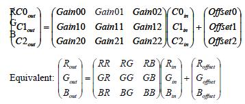
The following properties and functions can be used to configure this filter:
- mvIMPACT::acquire::ImageProcessing::colorTwistEnable
- mvIMPACT::acquire::ImageProcessing::colorTwistInputCorrectionMatrixEnable
- mvIMPACT::acquire::ImageProcessing::colorTwistInputCorrectionMatrixMode
- mvIMPACT::acquire::ImageProcessing::colorTwistInputCorrectionMatrixRow0
- mvIMPACT::acquire::ImageProcessing::colorTwistInputCorrectionMatrixRow1
- mvIMPACT::acquire::ImageProcessing::colorTwistInputCorrectionMatrixRow2
- mvIMPACT::acquire::ImageProcessing::colorTwistOutputCorrectionMatrixEnable
- mvIMPACT::acquire::ImageProcessing::colorTwistOutputCorrectionMatrixMode
- mvIMPACT::acquire::ImageProcessing::colorTwistOutputCorrectionMatrixRow0
- mvIMPACT::acquire::ImageProcessing::colorTwistOutputCorrectionMatrixRow1
- mvIMPACT::acquire::ImageProcessing::colorTwistOutputCorrectionMatrixRow2
- mvIMPACT::acquire::ImageProcessing::colorTwistResultingMatrixRow0
- mvIMPACT::acquire::ImageProcessing::colorTwistResultingMatrixRow1
- mvIMPACT::acquire::ImageProcessing::colorTwistResultingMatrixRow2
- mvIMPACT::acquire::ImageProcessing::colorTwistRow0
- mvIMPACT::acquire::ImageProcessing::colorTwistRow1
- mvIMPACT::acquire::ImageProcessing::colorTwistRow2
Memory Consumption
This filter does require NO additional memory.
Gamma Filter
Gamma correction is a non-linear operation on image data which is nowadays used to compensate for the also non-linear properties of the human vision. When gamma correction is applied to an image, the encoding bits of this image are more evenly distributed between bright and dark areas of the image, and as a result, the human eye perceives more information content. This filter can only turned on or off and applies a fixed gamma value to the image.
- Note
- This filter has not yet been published officially. Its interface might change without prior notice and it might only be available in special builds. Use it with care!
Memory Consumption
This filter does require NO additional memory.
Look-Up Table Filter (LUT)
This filter is responsible for the Look-Up table functionality. By using a Look-Up table, each pixel value may be mapped to a different one, providing the mechanism to transform the input range of brightness to another range of brightness defined by the user.
The following properties and functions can be used to configure this filter:
- mvIMPACT::acquire::ImageProcessing::LUTEnable
- mvIMPACT::acquire::ImageProcessing::LUTImplementation
- mvIMPACT::acquire::ImageProcessing::LUTInterpolationMode
- mvIMPACT::acquire::ImageProcessing::LUTMappingHardware
- mvIMPACT::acquire::ImageProcessing::LUTMappingSoftware
- mvIMPACT::acquire::ImageProcessing::LUTMode
- mvIMPACT::acquire::ImageProcessing::getLUTParameterCount()
- mvIMPACT::acquire::ImageProcessing::getLUTParameter()
Memory Consumption
This filter does require NO additional memory.
Soft Scaler Filter
This filter can re-scale the image to a user defined width and height using different interpolation algorithms.
The following properties and functions can be used to configure this filter:
- mvIMPACT::acquire::ImageDestination::scalerMode
- mvIMPACT::acquire::ImageDestination::scalerInterpolationMode
- mvIMPACT::acquire::ImageDestination::imageWidth
- mvIMPACT::acquire::ImageDestination::imageHeight
- mvIMPACT::acquire::ImageDestination::scalerAoiEnable
- mvIMPACT::acquire::ImageDestination::scalerAoiHeight
- mvIMPACT::acquire::ImageDestination::scalerAoiStartX
- mvIMPACT::acquire::ImageDestination::scalerAoiStartY
- mvIMPACT::acquire::ImageDestination::scalerAoiWidth
Memory Consumption
When active this filter will consume 1 buffer per allocated request object. The size of this buffer depends on the desired scaled width and height.
Channel Split Filter
The channel split filter, as the name implies, is able to split the image to separate channels, and concatenate them into a single image. The channels may be concatenated vertically or horizontally, depending on the settings chosen by the user. Also individual channels can be extracted from a multi-channel image.
Converting packed data to planar formats
This filter can be of great help if packed data comes from a device when planar data is needed. E.g. YUV411 or YUV422 packed data can be converted into a planar representation using this filter. Especially processing function the supply a line pitch will benefit from this approach. Even though the filter will output a single channel mono buffer this data can easily be re-interpreted in different ways. E.g. YUV411_UYYVYY_Packed data can be converted into YUV420 planar as defined by the FourCC code I420 like this:
- ChannelSplitEnable = bTrue
- ChannelSplitMode = csmVertical
The result will be a Mono8 image with 1.5 time the height of the original image. However in memory the data is arranged exactly as needed for the I420 format, thus
will become
thus simply treating the Mono8 buffer in a different way will then result in this buffer to be used as a YUV420 planar one!
The following properties and functions can be used to configure this filter:
- mvIMPACT::acquire::ImageProcessing::channelSplitEnable
- mvIMPACT::acquire::ImageProcessing::channelSplitMode
- mvIMPACT::acquire::ImageProcessing::channelSplitChannelIndex
- mvIMPACT::acquire::ImageProcessing::channelSplitDeinterlaceEnable
Memory Consumption
When active this filter will consume 1 buffer per allocated request objects of the same size as the buffer fed into it from any of the previous stages. The only exception will be when RGB planar data is fed into the filter and vertical splitting is selected. Then no additional memory will be consumed.
Watermark Generator Filter
The watermark generator filter is a simple filter which embeds a simple image (a cross-hair) into the original captured image data. Please note that this will permanently modify the image. The color of the pattern can be user defined if wanted but each color component will be applied to the corresponding channel of the image being processed then, thus for a mono image only the first color value will be taken into account and the result will be a mono buffer again. That means that it is not possible to generate a red cross-hair on a Mono8 image buffer.
- Note
- No official interface has been published for this filter yet. An application can bind to the properties from within the WatermarkGenerator lists of properties manually if needed.
Memory Consumption
This filter does require NO additional memory.
Rotation Filter
The rotation filter is a convenience filter which rotates the original captured image.
This filter allows rotating an image counterclockwise by a precise value in degrees (e.g. 36.756). The full ROI of the original image will be preserved, which for most angles results in the output image of this filter being larger than the input image. Empty regions in the corners of the rotated image will be painted grey. Currently only nearest neighbour interpolation is supported.
The following properties and functions can be used to configure this filter:
- mvIMPACT::acquire::ImageProcessing::rotationEnable
- mvIMPACT::acquire::ImageProcessing::rotationAngle
Memory Consumption
When active this filter will consume 1 buffer per allocated request object Depending on the rotation angle the size of this buffer might vary as the buffer is allocated with the dimensions of the bounding box of the rotated image.
Image Format Conversion Filter
This filter is located at the very end of the chain of filters. It allows converting the image that has been delivered either by the device or as the result of one or more of the processing filters into any other pixel format supported by Impact Acquire. This e.g. might help to fulfil the requirements by an application that demands a certain pixel format for it to execute its algorithms on.
The following properties and functions can be used to configure this filter:
Memory Consumption
When active this filter might consume 1 buffer per allocated request object of the same size as the resulting buffer passed to the application. Depending on the combination of input and output format of this filter sometimes no additional memory will be consumed. This might be the case whenever operations can happen inplace.
Final Output Stage
This is not an actual filter but a final node that is passed by the request until it is passed back to the user. There can be 2 situations when one additional copy operation for the image data is needed and this is handled here:
- When the device works with a fixed size DMA memory and cannot accept user allocated chunks of memory the data must be copied if a user supplied buffer has been attached to the request that has not been filled already(e.g. while converting raw Bayer data coming from the device into the user supplied RGB buffer)
- Some devices use an internal ring pool of DMA data. This will sometimes require copying the data even if no user supplied buffer has been attached to the request
Memory Consumption
When any of the above conditions are met this stage will consume 1 buffer per allocated request object of the same size as the resulting buffer passed to the application.
Post Processing Data Already Captured
Sometimes it might be desirable to apply a certain filter discussed here at a later moment in time or to an image that has already been captured an has been stored on disc. As the filter chain is part of the acquisition frameworks capture chain this is not directly possible but can be achieved using the mvVirtualDevice library. This library is capable of capturing images from a use definable folder on disc. Various other properties can be used to further configure the resulting frames. E.g. the AOI can be specified as well as a certain Bayer parity. See the class mvIMPACT::acquire::ImageDestination::CameraSettingsVirtualDevice for details.
Especially when combined with the FreeImage library as described in the Use Cases section of the mvVirtualDevice manual the most common file formats are supported.
mvIMPACT image processing (deprecated)
- Note
- mvIMPACT image processing library is not recommended for new designs. It will no longer be supported!
When additional image processing of the captured images is required as well the mvIMPACT image processing library can be used in connection with this capture interface. All image processing functions however will ask for a special image buffer format.
The device can deliver this format natively but the functions returning this data format will not by default be included into the interface thus allowing the usage of the capture interface only without the need to install the complete image processing library as well. To include the functions that will return mvIMPACT image processing library compliant buffers to the user application the main header of the library must be included BEFORE including the capture interface headers:
If this include order is used, the class mvIMPACT::acquire::Request will provide 2 additional versions of the method mvIMPACT::acquire::Request::getIMPACTImage that can be used to obtain images in an image processing library compatible format.