BVS CA-GVx-xxxxxx-xxxxxx
Dimensions
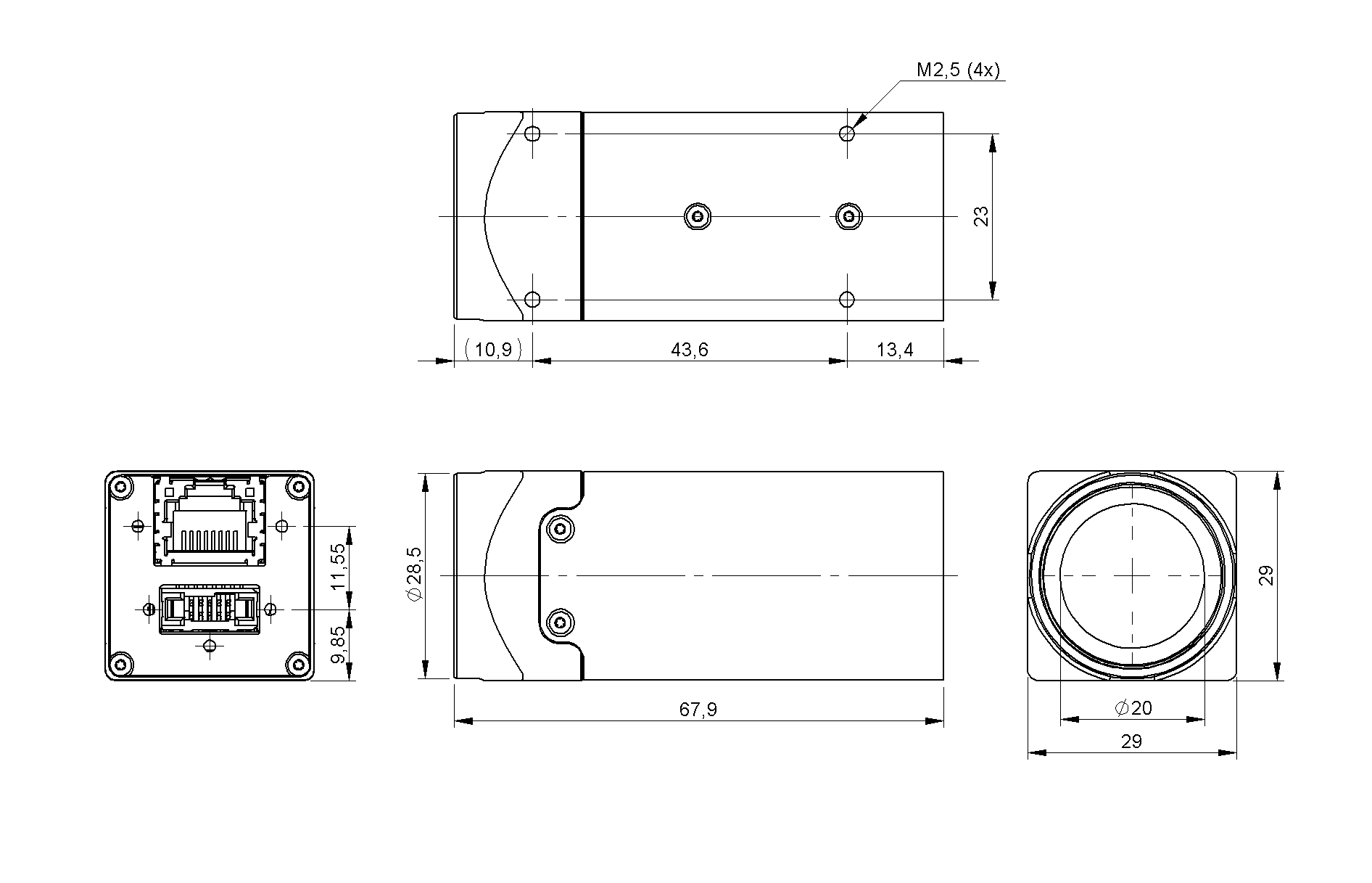
29 x 29 mm design
Figure 1: Connectors BVS CA-GV1-xxxxxx-xxxxxx
| Size of body (w x h x l) | 29 x 29 x 67.9 mm |
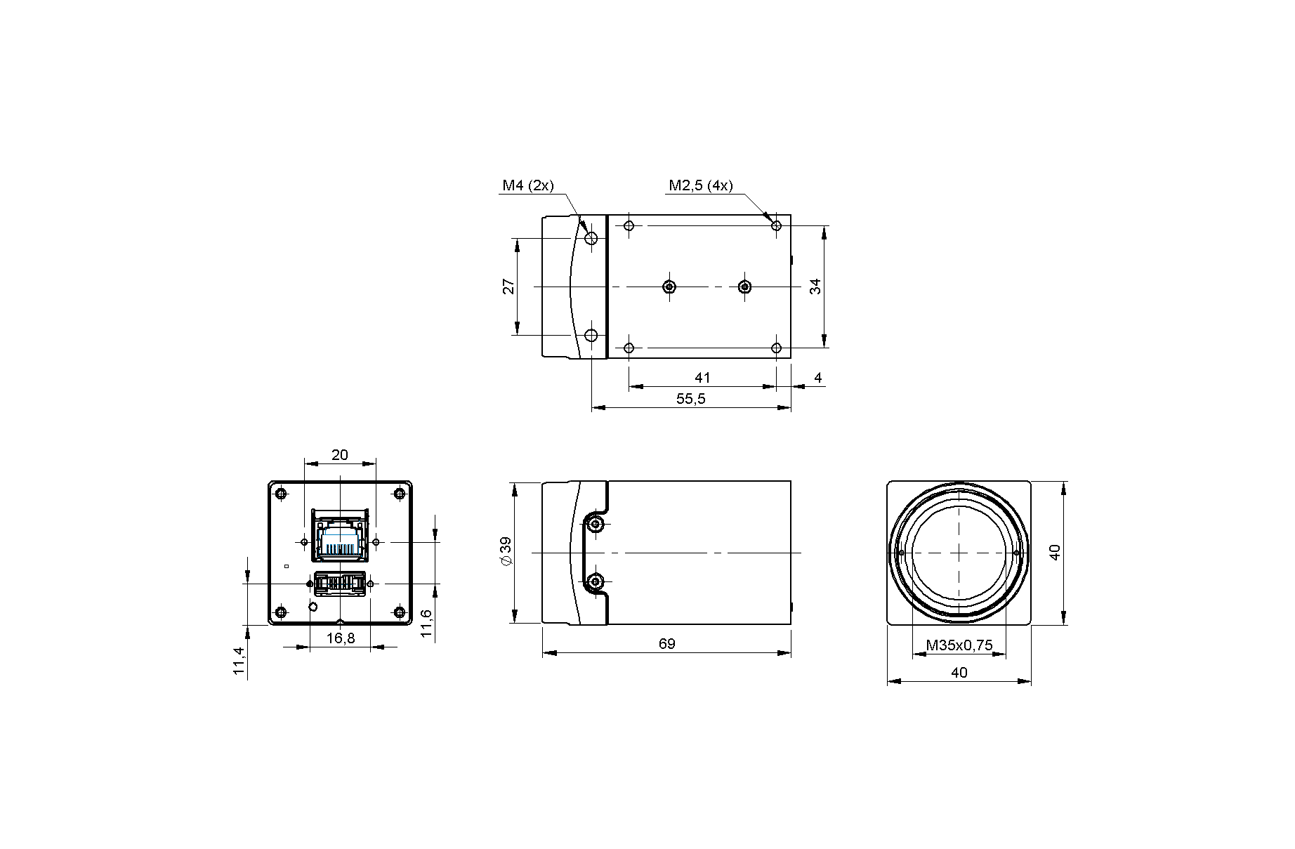
40 x 40 mm design
Figure 2: Connectors BVS CA-GV2-xxxxxx-xxxxxx
| Size of body (w x h x l) | 40 x 40 x 69 mm |
Connectors
I/O interface
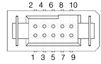
Figure 3: 10-pin (male; top view), digital I/O, power;
| 1 | GND | | | Black |
| 2 | PWR_IN | | Reference to GND | Red |
| 3 | Opto_In_GND | | Reference ground for OPTO_IN | Brown |
| 4 | Opto_Out_PWR_In | | Power for OPTO_OUT | Orange |
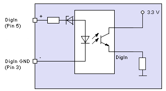
| 5 | Opto In1 | line1 | opto-isolated input, TTL/PLC | Yellow |
| 6 | Opto Out1 | line0 | opto-isolated output | Green |
| 7 | GPIO1 | line2 | Configurable input or Open Collector output. Reference to GND. | Blue |
| 8 | GPIO2 | line3 | Configurable input or Open Collector output. Reference to GND. | Violet |
| 9 | RS232 TX | | Serial interface RS232 TX. Reference to GND. | Grey |
| 10 | RS232 RX | | Serial interface RS232 RX. Reference to GND. | White |
* - cable family https://www.balluff.com/en-de/products/FHW02JC
Camera connector (male): Samtec TFM-105-02-L-DH or equivalent
The level of the digital inputs can be changed between TTL and mvPLC via the registry "LineFormat".
- Note
- Pin 3 to Pin 6 are galvanically isolated from the camera electronics.
- Pin 7 and Pin 8 are dual function pins.
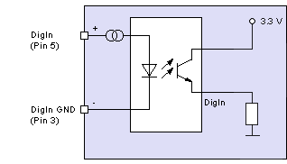
Electrical characteristics Opto In1
| Opto In1 TTL (via software) |
| VIL (low level input voltage) | 0 | | 1 | V |
| VIH (high level input voltage) | 2.5 | | 28 | V |
| IIH (high level input current TTL with 5V) | | | 5 | mA |
Figure 4: Opto In1 (TTL)
| Opto In1 PLC (default) |
| UOpto DigIn_LOW / VIL (low level input voltage) | 0 | | 8 | V |
| UOpto DigIn_HIGH / VIH (high level input voltage) | 11 | | 28 | V |
| IOpto DigIn_HIGH / IIH (high level input current PLC with 24V) | | | 8 | mA |
Figure 5: Opto In1 PLC
| Opto In1 PLC / TTL Speed |
| Switching frequency | | | 5 | MHz |
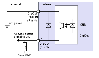
Electrical characteristics Opto Out1
| Opto Out1 |
| VOL (low level output voltage) | 0 | | 1 | V |
| VOH (high level output voltage) | 3 | | 28 | V |
| USW(sat) at ILoad = 150 mA | | 0.69 | 1 | V |
| ILoad Load current | | | 150 | mA |
Figure 6: DigOut with example circuit
| Switching characteristics |
| tON Turn-On time | at ILoad = 150 mA / VOH 24 V | 4 | us |
| tOFF Turn-Off time | 131 | us |
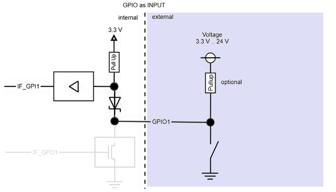
Electrical characteristics GPIO1/2
| GPIO as Input |
| VIL (low level input voltage) | 0 | | 0.5 | V |
| VIH (high level input voltage) | 1.8 | | 28 | V |
| IIL (low level input current) | | | 5 | mA |
| IIH (high level input current) | | | 1 | mA |
| Switching frequency | | | 5 | MHz |
Figure 7: GPIO as input
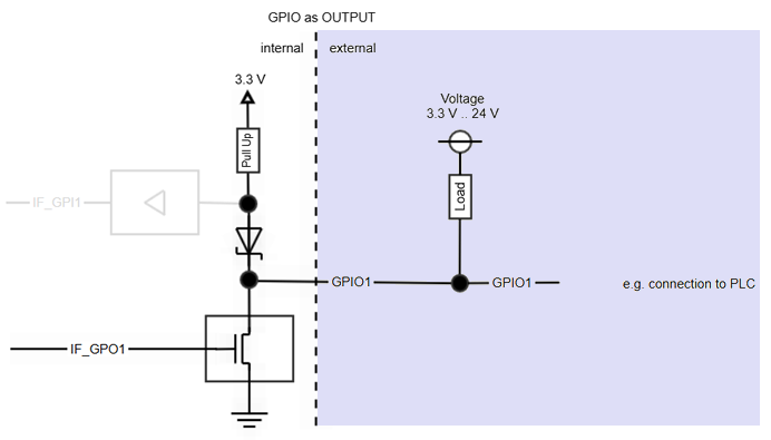
| GPIO as Output |
| UGPIO DIG_OUT_LOW / VOL (low level output voltage) | 0 | | 0.1 | V |
| UGPIO DIG_OUT_HIGH / VOH (high level output voltage) | 3 | | 28 | V |
| IDIG_OUT_LOW / IOL (low level output current PLC at 24 V) | | 20 | 50 | mA |
Figure 8: GPIO as open drain output - Attention
- "Damage of the output"
If the output exceeds the maximum permissible value, the output may be damaged.
Never exceed the value of IDIG_OUT_LOW / IOL above 50 mA.
| Switching characteristics |
| tON Turn-On time High-to-Low | at ILoad = 20 mA / VOH 3.3 V | | 50 | ns |
| tON Turn-On time High-to-Low | at ILoad = 20 mA / VOH 24 V | 70 | 100 | ns |
| tOFF Turn-Off time Low-to-High | 1.5 | 2 | us |
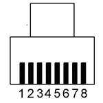
RJ45 Ethernet
With the -POE option, the camera is a class 2 compliant PoE device.
Figure 9: RJ45 pin numbering (female)
| 1 | BI_DA+ | bi | data positive |
| 2 | BI_DA- | bi | data negative |
| 3 | BI_DB+ | bi | data positive |
| 4 | BI_DC+ | bi | data positive |
| 5 | BI_DC- | bi | data negative |
| 6 | BI_DB- | bi | data negative |
| 7 | BI_DD+ | bi | data positive |
| 8 | BI_DD- | bi | data negative |
- Note
- The Ethernet signals are galvanically isolated from the camera electronics and camera housing.
RJ45 LED states
| Green light on | Link active |
| Yellow blink on | Data transmission |
Signal LED
The BVS CA-GV features a RGB LED. There are following states:
Typical start sequence (LLA)
- See also
- LLA
| FPGA loaded | White on |
| Self-test running | Green on |
| Waiting for Ethernet connection | White blink |
| Waiting for LLA (auto IP) | Green blink |
| Waiting for client | Blue on |
Typical start sequence (DHCP)
- See also
- DHCP
| FPGA loaded | White on |
| Self-test running | Green on |
| Waiting for Ethernet connection | White blink |
| Waiting for DHCP | Light blue blink |
| Waiting for client | Blue on |
Typical start sequence (Fixed IP)
- See also
- Fixed IP
| FPGA loaded | White on |
| Self-test running | Green on |
| Waiting for Ethernet connection | White blink |
| Waiting for client | Blue on |
General behavior
| Starting ImpactControlCenter |
| Connected, streaming off | Yellow on |
| Streaming on | Green on |
| Error |
| Red on |
Summary of components
| Image Memory | | - |
| Proc. Memory | | 512 MB |
| Inputs | | 1 |
| Type | opto-isolated |
| Outputs | | 1 |
| Type | opto-isolated |
| GPIO | | 2 |
| Ethernet | 2500/5000 Mbit | RJ45 |
| Optics | | |
| Lens Mount (Focal Distance) | C-mount (17.526 mm in air), optional TFL-mount |
| Lens Protrusion | max. 8 mm |
| Environment | | |
| Ambient Temperature | |
| Operation | 0..45 deg C / 30 to 80% RH non condensing |
| Storage | -20..60 deg C / 20 to 90% RH non condensing |
| | Protection class 1 | IP40 |
| Additional features | | Internal temperature sensor |
| Weight without lens | | approx. 71 g |
| Power supply (PWR_IN) | | |
| DC | 10.2 to 28 V |
| Pmax | 4.85 W |
| Reverse polarity protection | up to 28 V |
1 not evaluated by UL
Summary of advanced features
The following table shows an excerpt of the advanced features.
For the complete list, please use the "Product Comparison" in Appendix B. Product Comparison .