Loading...
Searching...
No Matches
BVS CA-UB1-0051H (5.1 Mpix [2592 x 1944])
Introduction
The CMOS sensor module (IMX335) incorporates the following features:
- resolution to 2592 x 1944 gray scale or RGB Bayer mosaic
- supports window AOI mode with faster readout
- rolling shutter / global reset release
- programmable readout timing with free capture windows and partial scan
- many trigger modes (free-running, hardware-triggered)
Details of operation
The sensor uses two acquisition modes:
- rolling shutter (mvShutterMode =
"RollingShutter") and - global reset release shutter (mvShutterMode =
"GlobalResetRelease").
With the rolling shutter the lines are exposed for the same duration, but at a slightly different point in time:
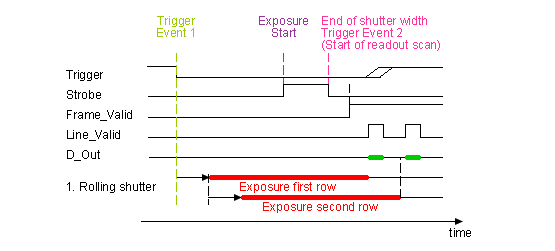
- Note
- Moving objects together with a rolling shutter can cause a smear in moving objects.
The global reset release shutter, which is only available in triggered operation, starts the exposure of all rows simultaneously and the reset to each row is released simultaneously, too. However, the readout of the lines is equal to the readout of the rolling shutter: line by line:
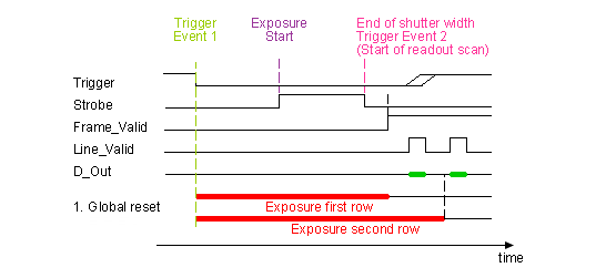
- Note
- This means, the bottom lines of the sensor will be exposed to light longer! For this reason, this mode will only make sense, if there is no extraneous light and the flash duration is shorter or equal to the exposure time.
Furthermore, the sensor offers two operating modes:
- free running mode (Overlapping exposure and readout)
- snapshot mode (Sequential exposure and readout) in triggered operation
Free running mode
In free running mode, the sensor reaches its maximum frame rate. This is done by overlapping erase, exposure and readout phase. The sensor timing in free running mode is fixed, so there is no control when to start an acquisition. This mode is used with trigger mode Continuous.
To calculate the maximum frames per second (FPSmax) in free running mode you will need following formula:
| Name | Value |
| InternalLineLength | 5200 |
| VerticalBlankLines | 48 |
| SensorInClock | 75 MHz |
                 InternalLineLength            ImageHeight + VerticalBlankLines
FrameTime =  ------------------------------ * ----------------------------------
                   SensorInClock                          1000
If exposure time is lower than frame time:
                 1
FPS_max =  ------------
            FrameTime
If exposure time is greater than frame time:
                 1
FPS_max =  --------------
            ExposureTime
Snapshot mode
In snapshot mode, the image acquisition process consists off several sequential phases:
Trigger
Snapshot mode starts with a trigger. This can be either a hardware or a software signal.
The following trigger modes are available:
| Mode | Description |
| Continuous | Free running, no external trigger signal needed. |
| OnFallingEdge | Each falling edge of trigger signal acquires one image. |
| OnRisingEdge | Each rising edge of trigger signal acquires one image. |
Erase, exposure and readout
All pixels are light sensitive at the same period of time. The whole pixel core is reset simultaneously and after the exposure time all pixel values are sampled together on the storage node inside each pixel. The pixel core is read out line-by-line after exposure.
- Note
- Exposure and read out cycle is carry-out in serial; that causes that no exposure is possible during read out.
The step width for the exposure time is 1 us.
Image data is then shifted out line-by-line and transferred to memory.
To calculate the maximum frames per second (FPSmax) in snapshot mode you will need following formula:
FPS_max =                  1
           -----------------------------------
                 FrameTime + ExposureTime
Use Cases
As mentioned before, "Global reset release" will only make sense, if a flash is used which is brighter than the ambient light. The settings in ImpactControlCenter will look like this:
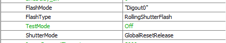
In this case, DigOut0 gets a high signal as long as the exposure time (which is synchronized with the GlobalResetRelease). This signal can start a flash light.
Frame rate calculator
- Note
- The calculator returns the max. frame rate supported by the sensor. Please keep in mind that it will depend on the interface and the used image format if this frame rate can be transferred.
- Note
- The exposure time step width is limited to the sensor's row time of 69.33 us and therefore
- auto exposure with very low exposure times will perform with relatively large increments and
- exposure mode = TriggerWidth (if available) will perform with a jitter corresponding to the row time.
Sensor Data
Device Structure
- CMOS image sensor (Type 1/2.8)
- Number of effective pixels: 2616 (H) x 1964 (V)
- Unit cell size: 2.0um (H) x 2.0um (V)
Characteristics
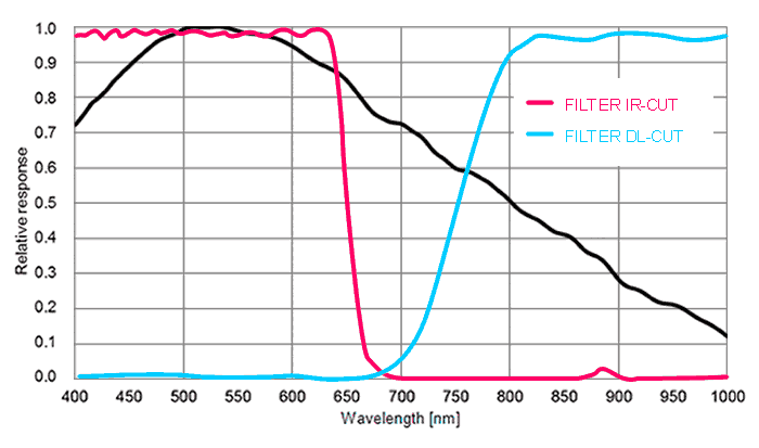
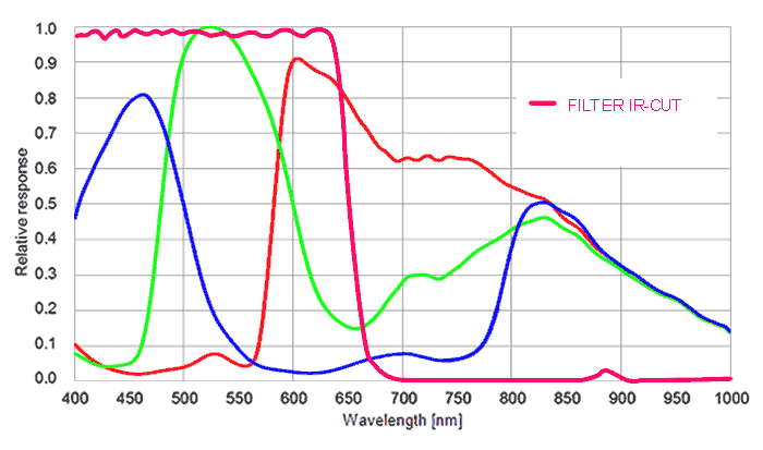
Color version
Gray scale version