Introduction
It is possible to use the BVS CA-MLC with a motorized lens mount without optical filter. To control this lens mount you use either ImpactControlCenter or the class MotorFocusControl from Impact Acquire for your own applications.
This camera option consists of a single-board camera module plus additional interface board. The camera is equipped with a board-to-wire connector on the interface board for opto-coupled I/O connection and a Mini USB. Other versions with TTL coupled inputs and outputs and without Mini USB connector are available on demand. There is no optical filter in the light path. For color applications Balluff supplies S-mount lenses with IR absorbing coating.
Important technical data of the motorized lens mount: (Consult Balluff for more detailed data, application notes and the full lens command reference manual)
| Lens Type | (Lens not included), accepts M12x0.5mm, smaller lenses to M8x0.35 with adapter from your lens supplier |
| Lens Weight* | < 5 grams |
| Travel Range | Up to 1.5 mm |
| Housing Dimension | 20 x 22 x 16 mm |
| Max Image Sensor Area (image sensor not included) | 17 x 17 x 1.25 mm (including 1/2" and 1/1.8" formats) |
| Speed | > 5 mm/s |
| Resolution | 0.5 um |
| Hysteresis | None |
| Repeatability Uni-directional | +/- 5 um |
| Bi-directional | +/- 20 um |
| Linear Accuracy | +/- 30 um |
| Angular alignment (Static tip/tilt) | > +/- 1 degree |
| Angular movement (Dynamic tip/tilt) | > +/- 0.15 degree |
| Static Concentricity | > +/- 0.25 mm |
| Dynamic Concentricity | > +/- 0.02 mm |
| Input Voltage | 3.1 to 3.6 Volts |
| Input Power** | < 0.5 Watts (5mm/s with 5g mass) < 0.13 Watts quiescent |
| Temperature / RH*** | 5 ° to 70 °C (lower possible) < 95% RH non-condensing |
| Mean Time Before Failure | > 2M Cycles (fixed orientation) 500K Cycles (random orientation) |
| Weight of module (without lens) | 5.8 grams |
| Compliance | CE / RoHS |
* Fixed orientation will allow for heavier lens operation. Consult Balluff if your lens does not fit or cannot be focused. ** Power depends on input voltage, speed & load. *** Consult Balluff if you have lower temperature requirements.
- Note
- By default, the motorized lens mount is shipped in
"closed loop mode". This means that the motor will move to and keep its absolute position in a permanent loop. Therefore you will hear a high frequent sound if you touch the lens or if you adjust the focus manually while the module is operating. For this reason, we recommend to use the"open loop mode"while adjusting the lens.
In fixed focus applications you might also consider switching to open loop mode. This will also extend the life time of the motor and reduce operation noise. Please note that the lens will remain at its position also in open loop mode due to mechanical friction.
The open loop mode can be set viaMotorFocusSendBuffer(value:"<20 0>") and then callMotorFocusSendeither in ImpactControlCenter or by programming.
Controlling motorized lens mount with ImpactControlCenter
Figure 1 shows a live snap of a scene with different focus planes.

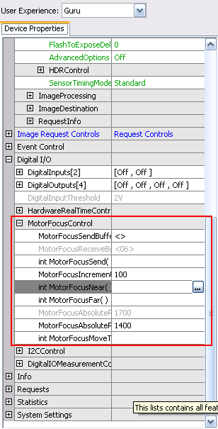
To control the motorized lens mount via ImpactControlCenter you have to change the "UserExperience" either to "Expert" or "Guru". Afterwards, there is a special section in "Digital I/O" called "MotorFocusControl" in the "Device Properties" tab:

This is a wrapper of the MotorFocusControl class which makes the following methods and properties available in the GUI:
- Properties:
MotorFocusAbsolutePositionCurrent:An integer property (read-only) storing the current absolute position (in encoder counts).MotorFocusAbsolutePositionDesired:An integer property storing an absolute position (in encoder counts) that will be used by subsequent calls to the MotorFocusMoveToAbsolutePositionDesired command.MotorFocusIncrement:An integer property storing an increment (in encoder counts) that will be used by subsequent calls to MotorFocusNear and MotorFocusFar commands.MotorFocusReceiveBuffer:A string property (read-only) that will contain answers sent by the motor focus controller.MotorFocusSendBuffer:A string property storing a command to be sent to the motor focus.
- Methods:
MotorFocusFar:Calling this function will cause the motor focus to move backward by MotorFocusIncrement encoder units.MotorFocusMoveToAbsolutePositionDesired:Calling this function will cause the motor focus to move to the position defined by the value of MotorFocusAbsolutePositionDesired.MotorFocusNear:Calling this function will cause the motor focus to move forward by MotorFocusIncrement encoder units.MotorFocusSend:Calling this function will send the value of MotorFocusSendBuffer to the hardware.
By clicking on the icon with the three dots (e.g. "MotorFocusNear()" in Figure 2), this method will be called using the set properties (e.g. "100" as "MotorFocusIncrement" value as shown in Figure 2).
The following explains the typical adjustment procedure:
-
Move the lens mount to the farthest position by applying
MotorFocusFarcommand as often as needed. - Switch off closed loop mode by using the command described above.
- Screw in lens and focus at infinity.
- Move to the nearest position and check MOD.
- Move to your working distance.
If your application does not require focusing at infinity you might set the lens mount to the middle position (1500 steps) and focus the lens for your working distance. This gives you equal focusing headroom in both directions. In this case please check that for MotorFocusNear the lens does not block the movement until Zero is reached.
Programming the motorized lens mount
If you want to program own application using the motorized lens mount, the Impact Acquire API offers the class MotorFocusControl which is described in MotorFocusControl class reference in the manual for the corresponding programming language at the manuals section.
- Note
- The following code snippets are C# pseudo code.
To use the MotorFocusControl class, you have to create an instance of the class:
// Initializing the device
DeviceManager deviceManager = new DeviceManager();
Device device = deviceManager.getDeviceByFamily("mvBlueFOX");

MotorFocusControl motorFocusControl = new MotorFocusControl(ref device);
- Note
- You can check, if the camera has a motorized lens mount at all via
"motorFocusControl.motorFocusIncrement.valid == false".
Afterwards, you can
"write()"(integer) /"writeS()"(string) and"read()"(integer) /"readS()"(string) the properties or"call()"the methods like
// setting the increment value to 100
motorFocusControl.motorFocusIncrement.write(100);
or
// moving the motor focus backwards by motorFocusIncrement
int status = motorFocusControl.motorFocusFar.call();
//getting the current position of the motor
int position = motorFocusControl.motorFocusAbsolutePositionCurrent.read();
- Note
- The call functions can be back while the motor is still moving. For this reason, it is necessary to create a method which will check if the motor still moves.
To get information from the motor you can use "motorFocusSend". The following example shows how you can get status and position of the motor. Furthermore, it shows how you can check, if the motor is still running:
...
int motorRunning = 0x4;
motorFocusControl.motorFocusSendBuffer.writeS("<10>");
motorFocusControl.motorFocusSend.call();
String s = motorFocusControl.motorFocusReceiveBuffer.readS();
if(s.Length != 29) return false;
// string is in hex
int status = Convert.ToInt32(s.Substring(4, 6), 16);

String positionStr = s.Substring(11, 8);
// the position as integer
int pos = Convert.ToInt32(positionStr, 16);

return (status & motorRunning) == motorRunning;
...
Sending the command "<10>" will return the status and position with following format:
<10 SSSSSS PPPPPPPP EEEEEEEE>
SSSSSSis the motor status (6-digit hex format, 24 bit unsigned integer),PPPPPPPPis the absolute position in encoder counts (8-digit hex format, 32-bit signed integer) andEEEEEEEEis the position error in encoder counts (8-digit hex format, 32-bit signed integer)
"Motor status values"
| Bit | Description | Values |
| 0 | Reserved | N/A |
| 1 | Motor direction | 0 = Reverse 1 = Forward |
| 2 | Running | 1 = Motor is running |
| 3 | Motor interlock | 1 = Motor is disconnected |
| 4 | Numbered burst mode | 1 = Fixed number of bursts in progress |
| 5 | Timed run | 1 = Timed free run in progress |
| 6 | Multiplexed axis | 1 = Multiplexed axis (e.g., SQ-2306, 2206) |
| 7 | Controller status | 1 = Under computer control (analog servo control, if supported, is not available) |
| 8 | Reserved | |
| 9 | Forward limit | 1 = Forward travel limit reached |
| 10 | Reverse limit | 1 = Reverse travel limit reached |
| 11 | Motor burst or amplitude mode | 1 = Amplitude mode (always used in closed-loop mode). 1 = Burst mode (200 Hz) |
| 12 - 15 | Reserved | N/A |
| 16 | Encoder count error | 1 = An error was detected in the encoder quadrature signal. Cleared by sending command <07>. |
| 17 | Zero reference enabled | 1 = Encoder zero reference mark detection is enabled |
| 18 | Motor on target | 1 = Encoder position error is zero |
| 19 | Motor moving toward target | 1 = Motor is moving toward a target position; appears after command <08> or move step command <06>. Once the target is reached, bit 19 is set to zero. |
| 20 | Maintenance mode enabled | 1 = Controller will actively hold the last target position
|
| 21 | Closed loop enabled | 1 = Motion commands use the encoder for feedback |
| 22 | Motor accelerating | 1 = The motor is accelerating to the desired velocity (set at the start of closed-loop motion) 0 = Required motor speed is reached, motor is decelerating, or motor is stopped |
| 23 | Stalled | 1 = The position error exceeds the stall detection threshold |
Following two examples will show, how the motor status value will look like (using the code snippet before):
Example 1: Motor doesn't move (return = false)
Status:
   Hex: 340080
   Dec: 3408000
Binary:  0011  0100  0000  0000  1000  0000
        23-20 19-16 15-12 11-08 07-04 03-00 => bit 2 is 0

motorRunning would be 4 = 0000 0000 0000 0000 0000 0100
(status & motorRunning) = 0 => return false
Example 2: Motor does move (return = true)
Status:
   Hex: 380086
   Dec: 3670150
Binary:  0011  1000  0000  0000  1000  0110
        23-20 19-16 15-12 11-08 07-04 03-00 => bit 2 is 1

(status & motorRunning) = 4 => return true
Example 3: Something a little more complex
This shows a more complex piece of code of how the motor focus can be used.
