Loading...
Searching...
No Matches
Take two images with different expose times after an external trigger (HRTC)
- Note
- Please have a look at the Hardware Real-Time Controller (HRTC) chapter for basic information.
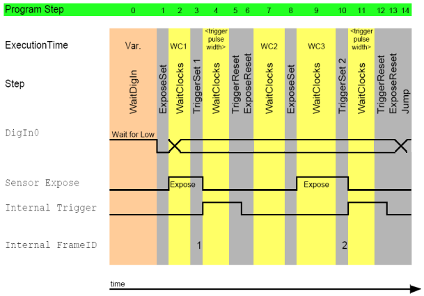
The following code shows the solution in combination with a CCD model of the camera. With CCD models you have to set the exposure time using the trigger width.
0.  WaitDigin DigIn0->Off
1.  ExposeSet
2.  WaitClocks <expose time image1 - 10us> (= WC1)
3.  TriggerSet 1
4.  WaitClocks <trigger pulse width>
5.  TriggerReset
6.  ExposeReset
7.  WaitClocks <time between 2 acquisitions - expose time image1 - 10us> (= WC2)
8.  ExposeSet
9.  WaitClocks <expose time image2 - 10us> (= WC3)
10. TriggerSet 2
11. WaitClocks <trigger pulse width>
12. TriggerReset
13. ExposeReset
14. Jump 0

<trigger pulse width> should not less than 100us.
- Note
- Due to the internal loop to wait for a trigger signal, the WaitClocks call between "TriggerSet 1" and "TriggerReset" constitute 100 us . For this reason, the trigger signal cannot be missed.
- Before the ExposeReset, you have to call the TriggerReset otherwise the normal flow will continue and the image data will be lost!
- The sensor expose time after the TriggerSet is 0 us .
Using a CMOS model (e.g. the mvBlueFOX-MLC205), a sample with four consecutive exposure times (10ms / 20ms / 40ms / 80ms) triggered just by one hardware input signal would look like this:
0.  WaitDigin DigIn0->On
1.  TriggerSet
2.  WaitClocks 10000 (= 10 ms)
3.  TriggerReset
4.  WaitClocks 1000000 (= 1 s)
5.  TriggerSet
6.  WaitClocks 20000 (= 20 ms)
7.  TriggerReset
8.  WaitClocks 1000000 (= 1 s)
9.  TriggerSet
10. WaitClocks 40000 (= 40 ms)
11. TriggerReset
12. WaitClocks 1000000 (= 1 s)
13. TriggerSet
14. WaitClocks 80000 (= 40 ms)
15. TriggerReset
16. WaitClocks 1000000 (= 1 s)
17. Jump 0
- See also
- This second sample is also available as an
rtpfile: MLC205_four_images_diff_exp.rtp.