Loading...
Searching...
No Matches
Take two images after one external trigger (HRTC)
- Note
- Please have a look at the Hardware Real-Time Controller (HRTC) chapter for basic information.
0. WaitDigin DigIn0->Off
1. TriggerSet 1
2. WaitClocks <trigger pulse width>
3. TriggerReset
4. WaitClocks <time between 2 acquisitions - 10us> (= WC1)
5. TriggerSet 2
6. WaitClocks <trigger pulse width>
7. TriggerReset
8. Jump 0

<trigger pulse width> should not less than 100us.
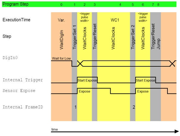
This program generates two internal trigger signals after the digital input 0 is going to low. The time between those internal trigger signals is defined by step (4). Each image is getting a different frame ID. The first one has the number 1, defined in the command (1) and the second image will have the number 2. The application can ask for the frame ID of each image, so well known which image is the first and the second one.