Loading...
Searching...
No Matches
Delay the expose start of the following camera (HRTC)
- Note
- Please have a look at the Hardware Real-Time Controller (HRTC) chapter for basic information.
- The use case Synchronize the cameras to expose at the same time shows how you have to connect the cameras.
If a defined delay should be necessary between the cameras, the HRTC can do the synchronization work.
In this case, one camera must be the master. The external trigger signal that will start the acquisition must be connected to one of the cameras digital inputs. One of the digital outputs then will be connected to the digital input of the next camera. So camera one uses its digital output to trigger camera two. How to connect the cameras to one another can also be seen in the following image:
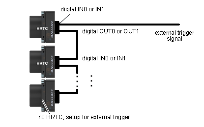
Assuming that the external trigger is connected to digital input 0 of camera one and digital output 0 is connected to digital input 0 of camera two. Each additional camera will then be connected to it predecessor like camera 2 is connected to camera 1. The HRTC of camera one then has to be programmed somehow like this:
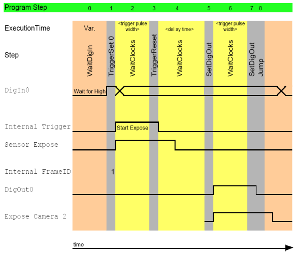
0. WaitDigin DigIn0->On
1. TriggerSet 0
2. WaitClocks <trigger pulse width>
3. TriggerReset
4. WaitClocks <delay time>
5. SetDigout DigOut0->On
6. WaitClocks 100us
7. SetDigout DigOut0->Off
8. Jump 0

<trigger pulse width> should not less than 100us.
When the cameras are set up to start the exposure on the rising edge of the signal <delay time> of course is the desired delay time minus <trigger pulse width>.
If more than two cameras shall be connected like this, every camera except the last one must run a program like the one discussed above. The delay times of course can vary.