Introduction
The CMOS sensor module (MT9M001) incorporates the following features:
- resolution to 1280 x 1024 gray scale
- supports window AOI mode with faster readout
- dynamic range 61dB
- programmable analog gain (0..12dB)
- progressive scan sensor (no interlaced problems!)
- rolling shutter
- programmable readout timing with free capture windows and partial scan
- many trigger modes (free-running, hardware-triggered)
Details of operation
The sensor uses following acquisition mode:
- rolling shutter (ShutterMode =
"ElectronicRollingShutter").
With the rolling shutter the lines are exposed for the same duration, but at a slightly different point in time.
- Note
- Moving objects together with a rolling shutter can cause a shear in moving objects.
Furthermore, the sensor offers one operating mode:
- snapshot mode (which means sequential exposure and readout)
Snapshot mode
In snapshot mode, the image acquisition process consists off several sequential phases:
Trigger
Snapshot mode starts with a trigger. This can be either a hardware or a software signal.
The following trigger modes are available:
| Mode | Description |
| Continuous | Free running, no external trigger signal needed. |
| OnDemand | Image acquisition triggered by command (software trigger). |
| OnLowLevel | As long as trigger signal is Low camera acquires images with own timing. |
| OnHighLevel | As long as trigger signal is High camera acquires images with own timing. |
| OnFallingEdge | Each falling edge of trigger signal acquires one image. |
| OnRisingEdge | Each rising edge of trigger signal acquires one image. |
| OnHighExpose | Each rising edge of trigger signal acquires one image, exposure time corresponds to pulse width. |
| OnLowExpose | Each falling edge of trigger signal acquires one image, exposure time corresponds to pulse width. |
| OnAnyEdge | Start the exposure of a frame when the trigger input level changes from high to low or from low to high. |
- See also
- For detailed description about the trigger modes (https://www.balluff.com/en-de/online-manuals-mv [Impact Acquire API])
- C: TCameraTriggerMode
- C++: mvIMPACT::acquire::TCameraTriggerMode
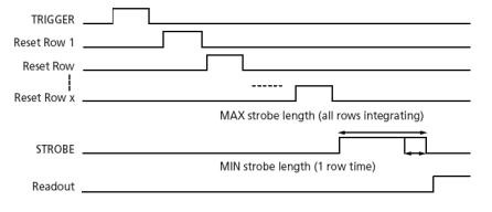
Erase, exposure and readout
After the trigger pulse, the complete sensor array is erased. This takes some time, so there is a fix delay from about 285 us between the trigger pulse on digital input 0 and the start of exposure of the first line.
The exact time of exposure start of each line (except the first line) depends on the exposure time and the position of the line. The exposure of a particular line N is finished when line N is ready for readout. Image data is read out line-by-line and transferred to memory (see: https://www.balluff.com/de-en/whitepapers/cmos-sensors-with-rolling-shutter).
Exposure time is adjustable by software and depends on the image width. To calculate the exposure step size you will need following formula:
LineDelay = 0
PixelClkPeriod =    1
                 --------
                 PixelClk

RowTime = ( ImageWidth + 244 + LineDelay ) * PixelClkPeriod

RowTime = MinExposurTime = ExposureStepSize
Image data is then shifted out line-by-line and transferred to memory.
To calculate the maximum frames per second (FPSmax) in snapshot mode you will need following formula:
FrameTime = (ImageWidth + 244) * ((ImageHeight + 16) / PixelClock)
FPS_max =                   1
           -----------------------------------
                  FrameTime + ExposureTime
CMOS Timing in Snapshot mode
Frame rate calculator
- Note
- The calculator returns the max. frame rate supported by the sensor. Please keep in mind that it will depend on the interface and the used image format if this frame rate can be transferred.
Sensor Data
Device Structure
- Progressive scan CMOS image sensor
- Image size: 6.66(H)x5.32(V)mm (Type 1/2")
- Number of effective pixels: 1280 (H) x 1024 (V)
- Unit cell size: 5.2um (H) x 5.2um (V)
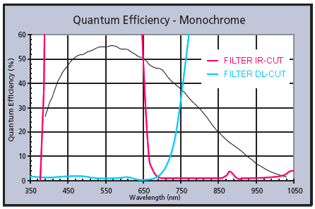
Characteristics
Gray scale version