Working with the I2C interface (I2C Control)
Introduction
As mentioned in the Device specific interface layout section of the Impact Acquire API manuals, the "I2CControl" is a feature which allows the mvBlueFOX device to communicate with custom-specific peripherals via the I2C interface.
Setting up the device
The following steps will explain how to connect the mvBlueFOX with an I2C device. In this use case, a LM75 I2C Digital Temperature Sensor is used:
- Start ImpactControlCenter
- Initialize the mvBlueFOX device
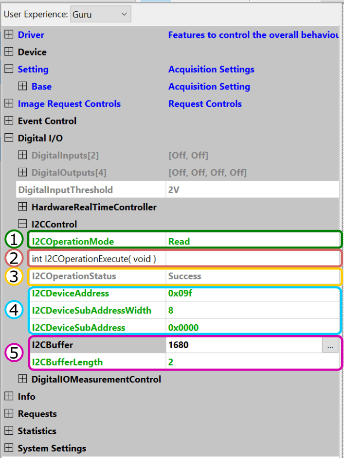
- Navigate to "Digital I/O -> I2CControl"
-
Enter the connection settings to address the I2C device memory (4).
E.g. to read the temperature of the example sensor, set I2CDeviceAddress to "0x09F". - Set I2CDeviceSubAddress to "0x00", because reading the temperature of this sensor does not need a sub address.
- Set I2CBufferLength (5) to 2, because this sensor stores the temperature in a register of two bytes length.
- Set the I2COperationMode (1) to Read. The least significant bit (LSB) of the device address will automatically be overwritten by 0 for writing and by 1 for reading.
- Navigate to the int I2COperationExecute( void ) function (2). Click on the 3 dots next to the function name or right-click on the command and then select Execute from the context menu to send the current message to the I2C device.
- The I2COperationStatus property (3) will display if the operation was successful.
- On success, the data is now displayed in the I2CBuffer property (5). This value is a hexadecimal number and needs to be interpreted depending on the I2C device.
- Note
- The following I2C addresses will be blocked for access from an application:
i2c address range affected devices 0x20-0x3F all mvBlueFOX devices 0x66-0x67 all mvBlueFOX devices 0x90-0x91 mvBlueFOX-200w only 0xA0-0xA3 all mvBlueFOX devices 0xA6-0xA7 all mvBlueFOX devices 0xBA-0xBB mvBlueFOX-202a and mvBlueFOX-205 only
Programming the I2C interface
The following lines of source code are meant to give an overview of the possibilities of the I2CControl class.
I2CControl i2cc( pBF ); // assuming 'pBF' to be a valid 'Device*' instance to an mvBlueFOX device
if( i2cc.I2COperationMode.isValid() )
{
  // direct property access
  i2cc.I2CBufferLength.write( 0 );
  i2cc.I2COperationMode.write( I2ComRead );
  assert( ( i2cc.I2COperationExecute.call() == DMR_INVALID_PARAMETER ) && "Unexpected driver behaviour" );
  assert( ( i2cc.I2COperationStatus.read() == I2CosNotEnoughData ) && "Unexpected driver behaviour" );
  i2cc.I2CBufferLength.write( 1 );
  // assuming we write to an invalid address
  assert( ( i2cc.I2COperationExecute.call() == DMR_EXECUTION_FAILED ) && "Unexpected driver behaviour" );
  assert( ( i2cc.I2COperationStatus.read() == I2CosFailure ) && "Unexpected driver behaviour" );
  i2cc.I2COperationMode.write( I2ComWrite );
  i2cc.I2CBuffer.writeBinary( string() );
  assert( ( i2cc.I2COperationExecute.call() == DMR_INVALID_PARAMETER ) && "Unexpected driver behaviour" );
  assert( ( i2cc.I2COperationStatus.read() == I2CosNotEnoughData ) && "Unexpected driver behaviour" );
  {
    char binData[2] = { 'A', 'B' };
    i2cc.I2CBuffer.writeBinary( string(binData, sizeof(binData)) );
  }
  // assuming we write to an invalid address
  assert( ( i2cc.I2COperationExecute.call() == DMR_EXECUTION_FAILED ) && "Unexpected driver behaviour" );
  assert( ( i2cc.I2COperationStatus.read() == I2CosFailure ) && "Unexpected driver behaviour" );
  // Write some data. This will only work if several conditions are met:
  // - there is a device that can be written to at address 0xA6
  // - the sub-address 0x04 is valid
  // - the device is designed to work with 8 bit sub-addresses
  // - the device can deal with 9 bytes in a single command
  i2cc.I2CDeviceAddress.write( 0xA6 );
  i2cc.I2CDeviceSubAddress.write( 0x04 );
  i2cc.I2CDeviceSubAddressWidth.write( 8 );
  {
    char binData[9] = { 'D', 'E', 'A', 'D', ' ', 'B', 'E', 'E', 'F' };
    i2cc.I2CBuffer.writeBinary( string( binData, sizeof( binData ) ) );
  }
  i2cc.I2COperationMode.write( I2ComWrite );
  int I2COperationExecuteResult = i2cc.I2COperationExecute.call();
  if( I2COperationExecuteResult != DMR_NO_ERROR )
  {
    printf( "'I2COperationExecute' write failed. Return value: %s(%d).\n", ImpactAcquireException::getErrorCodeAsString( I2COperationExecuteResult ).c_str(), I2COperationExecuteResult );
  }
  printf( "'I2COperationStatus' after write: %s.\n", i2cc.I2COperationStatus.readS().c_str() );
  // Read some data. Similar condition as for write apply
  const int bytesToRead = 4;
  i2cc.I2CDeviceAddress.write( 0xA8 );
  i2cc.I2CDeviceSubAddress.write( 0x00 );
  i2cc.I2CDeviceSubAddressWidth.write( 8 );
  i2cc.I2CBufferLength.write( bytesToRead ); // read 'bytesToRead' bytes
  i2cc.I2COperationMode.write( I2ComRead );
  i2cc.I2COperationExecute.call();
  I2COperationExecuteResult = i2cc.I2COperationExecute.call();
  if( I2COperationExecuteResult != DMR_NO_ERROR )
  {
    printf( "'I2COperationExecute' read failed. Return value: %s(%d).\n", ImpactAcquireException::getErrorCodeAsString( I2COperationExecuteResult ).c_str(), I2COperationExecuteResult );
  }
  printf( "'I2COperationStatus' after read: %s.\n", i2cc.I2COperationStatus.readS().c_str() );
  if( i2cc.I2CBuffer.binaryDataBufferSize() != bytesToRead )
  {
    printf( "'I2CBuffer' reports %d bytes of data while %d bytes where expected.\n", i2cc.I2CBuffer.binaryDataBufferSize(), bytesToRead );
  }
  // usage of the convenience functions
  i2cc.I2CWrite( 0xA4, 0x00, 8, string("TEST") );
  const string i2cReadBuffer = i2cc.I2CRead( 0xA4, 0x00, 8, 4 );
}
else
{
  printf( "I2CControl not available.\n" );
}